Understanding Control Valve Maintenance & Service in Your Operations
Maintenance & Service for control valve systems represents one of the most overlooked yet essential aspects of industrial plant management. As a distributor with 35+ years of experience serving Southeast Asian industrial operations, 3G Electric has observed that many plant shutdowns stem not from major pump failures, but from small valve control issues that cascade into system failures.
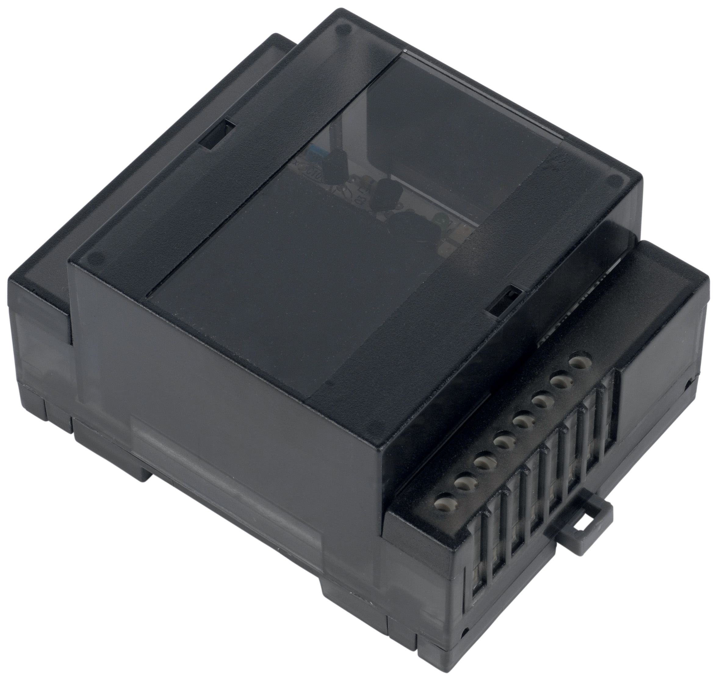
Control valves—particularly solenoid valves like the Elektrogas EVRM NA 7 solenoid valve—regulate fluid and gas flow, maintain pressure setpoints, and protect equipment from dangerous overpressure conditions. When these components fall outside specification, entire production lines can experience erratic pressure, contamination introduction, or catastrophic component damage. This guide equips plant managers with the knowledge to establish systematic Maintenance & Service protocols that prevent costly downtime.
Singapore's tropical climate, with high humidity, salt spray exposure near coastal areas, and 24/7 industrial operations, creates unique maintenance challenges. Your control valves face accelerated corrosion, moisture ingress, and thermal cycling that demand more aggressive preventive care than temperate-zone operations.
Section 1: Diagnostic Protocols for Solenoid Valve Performance
Establishing Baseline Performance Metrics
Effective Maintenance & Service begins with understanding your system's normal operating state. Before implementing any maintenance schedule, capture baseline data for each critical control valve:
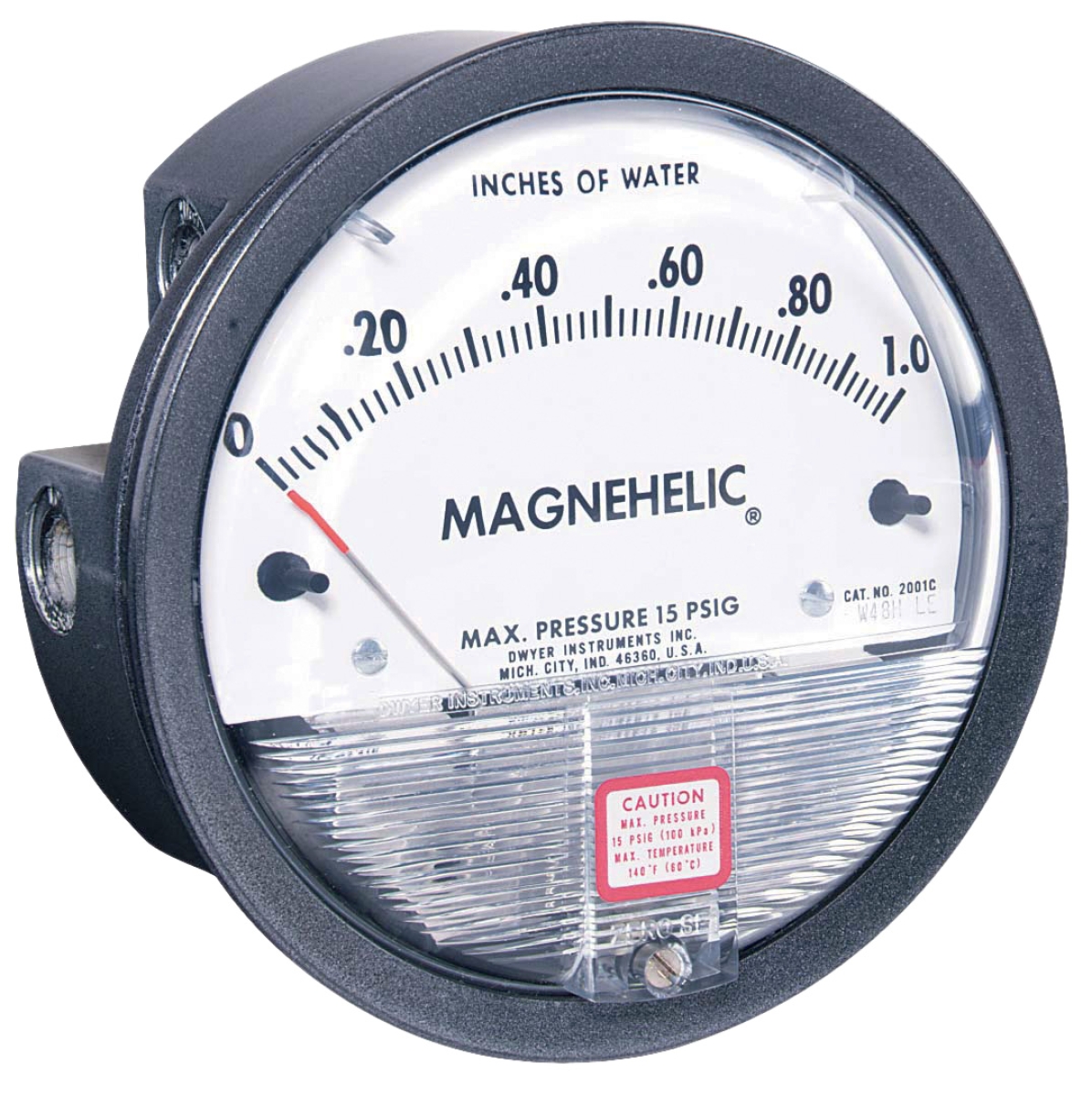
- Pressure differential across the valve (measured in bar or kPa using precision gauges like the Dwyer Magnehelic pressure gauge)
- Coil voltage and amperage (solenoids should draw rated current within ±5%)
- Response time from solenoid energization to valve opening (typically 50–150 milliseconds depending on design)
- Leakage rate when the valve is in the closed position
- Ambient temperature and humidity where the valve is mounted
For a solenoid valve rated at 600 Mbar like the EVRM NA 7, establish that it consistently maintains this pressure without drift. Pressure creep—gradual increase over minutes or hours—indicates internal seal degradation and warrants immediate replacement.
Weekly Visual Inspection Routine
Assign a technician to perform 15-minute weekly inspections of all critical solenoid valve installations:
- Check for external corrosion on the valve body, coil housing, and electrical connections. Singapore's salt spray environment accelerates rust formation; prioritize valves within 5 km of coastal areas for more frequent inspection.
- Verify cable connections are secure and show no green or white oxidation on connectors (oxidation increases contact resistance and coil dropout risk).
- Listen for audible clicking when the solenoid energizes—absence of clicking indicates possible coil failure or stuck plunger.
- Feel for heat generation on the coil housing (it should be warm, not hot—excessive heat suggests electrical overstress).
- Inspect gauge connections for leaks and ensure pressure readings align with expected setpoints.
Monthly Pressure and Electrical Testing
Combine mechanical observation with precision instrumentation. Using the Dwyer pressure gauge, measure pressure differential across the valve under full operational load once monthly:
1. Isolate the valve from downstream equipment if safely possible.
2. Connect the gauge to both inlet and outlet ports.
3. Energize the solenoid and note pressure drop across the valve opening.
4. De-energize and measure internal leakage over 5 minutes (acceptable leakage is typically <0.5% of system flow).
5. Record all values in a maintenance log with date, time, operator name, and ambient temperature.
Electrical testing should verify coil resistance matches manufacturer specifications (typically 20–40 ohms for standard 24 VDC solenoids). Use a digital multimeter to measure coil-to-ground resistance; values below 2 MΩ indicate moisture ingress and necessitate coil replacement.
Section 2: Preventive Maintenance Schedules Tailored to Singapore Conditions
Humid Environment Protocol
Singapore's relative humidity often exceeds 80% year-round, creating aggressive conditions for electrical components. Implement these preventive measures:
- Apply moisture-resistant coatings to solenoid coils and connectors every 18 months. Use epoxy or polyurethane coatings rated for IP54 or higher.
- Install desiccant cartridges in valve cable junction boxes. Check and replace cartridges quarterly (every 3 months in monsoon season).
- Position pressure gauges vertically to prevent water collection in gauge wells. Use Dwyer gauges with glycerin fill to reduce needle oscillation and shield internal components from moisture.
- Seal all threaded connections with PTFE tape and threadlocker compound (Loctite 243 grade) to prevent moisture intrusion at NPT ports.
Filtration and Fluid Purity Maintenance
Contaminated fluids degrade solenoid valve spools and destroy seals within weeks. Establish strict fluid management:
- Test fluid contamination using ISO 4406 particle counting every 250 operating hours. Solenoid valve systems require ISO 4406 16/14/11 cleanliness minimum; aim for 15/13/10 for extended valve life.
- Replace or backflush suction filters when pressure differential exceeds 0.5 bar above baseline.
- Implement offline fluid conditioning for plants operating continuously. Singapore's heat and humidity accelerate fluid oxidation; consider a portable filtration cart for weekly offline circulation through a 3 micron filter.
- Monitor fluid temperature continuously. Operating above 60°C accelerates seal degradation in solenoid valve coils; implement cooling or reduce operating pressure if sustained elevation occurs.
Component Replacement Strategy
Despite excellent Maintenance & Service, solenoid valve components reach end-of-life and must be replaced on schedule:
- Solenoid coils: Replace every 3–4 years in tropical climates (versus 5–7 years in temperate regions). Keep spare coils matched to each installed valve model in stock.
- Internal seals and spools: Replace during coil replacement (approximately 15–20% of component cost). This prevents premature failure of new coils.
- Pressure relief cartridges (if equipped): Replace every 2 years or after any system overpressure event.
- Connector and cable assemblies: Replace every 4 years or immediately if corrosion reaches the cable jacket.
Section 3: System-Level Pressure Management and Gearbox Integration
Coordinating Solenoid Valves with Pump Drive Systems
Solenoid valve performance depends on stable supply pressure from upstream pump systems. The Interpump GEARBOX RS500 provides consistent power transmission to positive displacement pumps like the Pratissoli KF30, which in turn supplies steady pressure to solenoid valve inlets.
Establish this relationship in your Maintenance & Service planning:
- Verify pump discharge pressure stability ±2 bar over 1 hour of continuous operation. Pressure oscillation indicates pump wear, cavitation, or drive belt slippage.
- Monitor gearbox temperature where power transmission couples the engine to the pump. The RS500 gearbox operates optimally at 60–85°C; sustained temperatures above 90°C indicate overload or inadequate lubrication.
- Inspect drive coupling alignment quarterly. Misalignment transmits shock loads to solenoid valve spools, causing premature wear and stuck plungers.
For the Pratissoli KF30 pump supplying 106 L/min at 200 bar, the solenoid valve controlling secondary circuits must be sized to handle this flow without exceeding rated pressure drop (typically 5–10 bar at maximum flow). If solenoid valve pressure differential exceeds specification, reduce pump displacement or implement parallel valve staging.
Pressure Gauge Placement and Monitoring
Multiple pressure measurement points create visibility into system health. Install Dwyer Magnehelic gauges at these critical locations:
1. Pump discharge: Establishes baseline system pressure and detects pump wear.
2. Solenoid valve inlet and outlet: Confirms proper pressure differential and identifies blockages.
3. Secondary circuit: Ensures downstream equipment operates within rated pressure.
4. Pilot pressure (if applicable): For pilot-operated solenoid valves, monitoring pilot pressure detects control signal problems.
Record all gauge readings hourly for high-criticality systems, or daily for standard operations. Trending pressure changes over weeks reveals gradual component degradation before failure occurs.
Integration with High-Pressure Spray Systems
Plants using spray coating equipment like the Pratissoli PISTOLA P560*LANCIA 1000 ATEX spray gun at 600 bar require solenoid valves capable of proportional or on-off control without pressure fluctuation. Implement this sequence:
- Supply pressure from the Pratissoli KF30 pump at constant 200 bar.
- Route flow through a pressure regulator set to 150 bar (75% of spray gun rating) to create margin.
- Place the solenoid valve downstream of the regulator to control spray gun activation.
- Install an accumulator (10% system volume minimum) between the regulator and solenoid valve to dampen pressure spikes when the gun trigger is released.
- Mount the Dwyer pressure gauge on the spray gun supply line to verify pressure stability during intermittent spray cycles.
This architecture prevents solenoid valve damage and extends spray gun service life from 2 years to 4+ years.
Section 4: Record-Keeping and Continuous Improvement
Digital Maintenance Logging System
Establish a centralized record for all Maintenance & Service activities. At minimum, log:
- Component identification: Valve model, serial number, installation location, and original commissioning date.
- Inspection findings: Pressure readings, electrical resistance, visual observations, and corrective actions taken.
- Replacement history: Original component cost, replacement cost (including labor), and reason for replacement.
- Downtime incidents: Date, duration, root cause, and whether the event was preventable through earlier maintenance.
After 12 months of data collection, analyze patterns. If a specific solenoid valve model fails consistently at 18 months, reduce replacement interval to 15 months and investigate supplier quality. If pressure drift begins at 8 weeks during monsoon season, increase humidity protection measures.
Supplier Relationships and Spare Parts Strategy
With 35+ years in industrial distribution, 3G Electric supports this data-driven approach. Maintain relationships with your equipment supplier to:
- Stock critical spare components locally. For the Elektrogas EVRM NA 7 solenoid valve, maintain 2 spare units on-site; 1 spare for the Dwyer pressure gauge; and 4 spare coil assemblies per unique valve model installed.
- Establish preferred pricing for bulk maintenance purchases. Volume commitments unlock discounts on filters, seals, and coils that reduce per-unit maintenance cost by 15–20%.
- Request technical data sheets and maintenance guides in English or your facility's primary language. Ensure maintenance documentation is accessible to all technicians.
Continuous Improvement Through Failure Analysis
When solenoid valve failure occurs, conduct root cause analysis:
- Was this preventable? Did pressure readings hint at impending failure 2–4 weeks prior?
- What contributed? Environmental factors (heat, humidity, contamination, voltage fluctuation)?
- What changes prevent recurrence? Earlier replacement interval, additional filtration, IP54+ enclosures, or different valve model selection?
Share these findings with your maintenance team quarterly. Over time, this institutional knowledge reduces emergency shutdowns and optimizes spare parts inventory.
Conclusion
Maintenance & Service for control valve systems requires discipline, data collection, and adaptation to Singapore's unique industrial environment. By implementing the diagnostic protocols, preventive schedules, and monitoring strategies outlined in this guide, plant managers can expect 50–70% reduction in solenoid valve-related downtime within 12 months. The modest investment in gauges, spare components, and technician training pays for itself through improved production reliability and extended equipment life.
3G Electric has supported thousands of Southeast Asian facilities through this transition from reactive to predictive Maintenance & Service management. Contact our technical team to audit your current solenoid valve and pressure control systems, or to discuss spare parts inventory strategies tailored to your facility.