Understanding Pumps & Compressors in HVAC Applications
Pumps & Compressors serve fundamentally different but equally essential roles in modern HVAC systems. Pumps circulate chilled or hot water through distribution networks, while compressors pressurize refrigerant to transfer thermal energy. For HVAC contractors, understanding the distinction between these components and their interaction within integrated systems is critical to delivering reliable installations.
With over 35 years of experience as an global industrial equipment distributor, 3G Electric has supported thousands of contractors in selecting and deploying the right Pumps & Compressors for diverse climate control applications. Whether you're installing a small commercial rooftop unit or a large-scale district cooling system, the principles of proper equipment selection and installation remain consistent.
The performance of your HVAC system depends on three interconnected factors: pump displacement and flow rate, compressor displacement and pressure rating, and the integration between components. Undersized pumps lead to inadequate water circulation and temperature stratification. Undersized compressors cannot achieve necessary discharge pressures. Conversely, oversized equipment wastes energy and increases operational costs. Contractors who master the balance between these components gain competitive advantages through superior system reliability and customer satisfaction.
Selecting the Right Pump for Your HVAC Installation
Displacement and Flow Rate Fundamentals
Pump selection begins with understanding displacement, measured in cubic centimeters per revolution (cc/rev). Displacement determines how much fluid the pump delivers per shaft rotation. For HVAC applications, typical residential systems operate between 3-15 GPM (gallons per minute), while commercial systems range from 50-500+ GPM depending on cooling capacity.
To calculate required pump displacement:
- Determine system cooling load in BTU/hour
- Calculate required flow rate using the formula: GPM = (BTU/hour) ÷ (500 × temperature differential in °F)
- Select pump displacement based on motor speed (typically 1,200-3,600 RPM for standard motors)
- Apply safety factor of 1.1-1.15 to account for friction losses and future system expansion
For example, a 120,000 BTU/hour system with a 10°F temperature differential requires approximately 24 GPM. At 1,800 RPM motor speed, this demands a pump with roughly 13-15 cc/rev displacement.
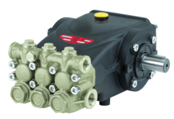
The Interpump PUMP E3B2515I R offers reliable displacement ratings suitable for mid-range commercial cooling applications, while the Interpump PUMP E3B2515 L provides configuration flexibility for retrofit installations where space constraints limit options.
Installation Best Practices
Proper pump installation directly impacts longevity and performance. Follow these critical steps:
Suction Line Configuration: Install the pump as close as possible to the water source with the suction line diameter 1-2 sizes larger than discharge. Avoid sharp bends and maintain suction lift below 6 feet. Use a suction strainer with 150-200 micron rating to prevent debris from entering the pump.
Discharge Line Setup: Size discharge lines according to velocity guidelines (4-6 feet per second for chilled water systems). Install a check valve downstream of the pump to prevent backflow. Include a pressure relief valve set 10-15% above system design pressure to protect against overpressurization.
Vibration Isolation: Mount pumps on resilient isolators to minimize noise transmission through building structures. Use flexible hose connections at pump inlet and outlet to absorb vibration. This is especially critical in occupied buildings where noise complaints affect customer satisfaction.
Shaft Alignment: Misalignment between motor and pump is a leading cause of premature bearing failure. Use laser alignment tools to ensure concentricity within 0.003 inches. Check alignment after installation, after seasonal startup, and annually during maintenance.
Compressor Integration and System Commissioning
Compressor Types and HVAC Applications
HVAC systems employ three primary compressor types: reciprocating, scroll, and rotary screw. Reciprocating compressors dominate smaller systems (under 20 tons) due to cost-effectiveness and part availability. Scroll compressors excel in the 3-30 ton range with superior efficiency. Rotary screw compressors serve large commercial and industrial applications (30+ tons).
Compressor displacement, like pump displacement, directly correlates to refrigerant volume handled per shaft revolution. A compressor rated for 50 cc/rev at 3,600 RPM moves 180,000 cc/minute (approximately 6.4 CFM). This calculation is essential because undersized compressors cannot reach discharge pressures necessary for condensing, while oversized units short-cycle and experience valve wear.
The Interpump PUMP E3B1515 DX*VALV.DX + GEARBOX RS500H demonstrates advanced configurations that integrate pump, valve, and gearbox components, offering contractors pre-assembled solutions that reduce field assembly time and potential installation errors.
System Commissioning Checklist
Before placing any HVAC system into operation, complete this commissioning sequence:
Pre-startup Verification:
- Verify pump motor rotation direction matches system piping configuration
- Confirm all electrical connections are tight and properly grounded
- Check refrigerant charge level against system nameplate specifications
- Inspect all solder joints for leaks using ultraviolet dye tracers
- Ensure proper oil charge in compressor (typically 50% of compressor displacement in cubic inches)
- Start system at minimum load while monitoring discharge and suction pressures
- Record baseline temperatures: entering water, leaving water, entering air, leaving air
- Measure electrical current draw on motor and compressor
- Listen for unusual noises indicating misalignment or bearing wear
- Observe pump operation for cavitation (characteristic sucking sound)
- Run system at design operating conditions for minimum 2 hours
- Monitor temperatures every 15 minutes to verify stability
- Check pump discharge pressure (typically 20-60 PSI for chilled water systems)
- Measure compressor discharge temperature (should not exceed 200°F for reciprocating units)
- Verify subcooling and superheat values align with design parameters
Documentation is critical. Photograph gauge readings, record all data on commissioning forms, and provide customers with baseline performance data for future comparison.
Maintenance Strategies and Performance Optimization
Preventive Maintenance Scheduling
Systematic maintenance extends equipment lifespan from typical 10-12 years to 15-20+ years while reducing emergency service calls that damage contractor reputation.
Monthly Tasks (performed during heating or cooling season):
- Inspect pump and motor for visible leaks
- Listen for cavitation or vibration changes
- Verify discharge and suction pressures remain within design ranges
- Check motor amperage; increases above baseline indicate bearing friction or impeller wear
- Change or clean suction line strainer
- Inspect flexible pump connections for deterioration
- Check compressor oil level in sight glasses
- Verify all electrical terminal connections remain tight
- Perform laser shaft alignment verification
- Send compressor oil sample for laboratory analysis (detects metal wear before failure)
- Replace pump discharge line filter element
- Inspect and test all safety valves for proper operation
- Clean condenser and evaporator coils to maintain heat transfer efficiency
- Replace pump and compressor seals as preventive measure
- Flush entire system if water quality testing reveals high hardness or pH issues
- Replace all refrigerant dryer cartridges
- Rebuild or replace expansion devices
Diagnosing Common Performance Issues
Reduced Cooling Capacity Despite Normal Pressures:
- Likely cause: Refrigerant charge loss or non-condensable gases
- Solution: Use electronic leak detector to identify breach points; recharge after evacuation
- Prevention: Apply ultraviolet dye during commissioning; inspect during quarterly maintenance
- Possible causes: Cavitation, worn pump impeller, or obstruction in suction line
- Diagnostic procedure: Increase suction lift by elevating water source; if pressure recovers, suction issue is confirmed
- Solution: Clean suction strainer, verify water inlet is fully submerged in reservoir
- Indicates inadequate cooling in discharge line or low refrigerant charge
- Immediate action: Reduce system load, increase condenser water flow
- Long-term fix: Verify pump is delivering design flow rate; adjust distributor valves if parallel piping configuration
- Usually caused by oversizing or thermostat malfunction
- Check thermostat swing settings; increase differential between on/off points
- If issue persists, verify compressor displacement matches system tonnage
The Interpump PUMP E3C1021 DXV.DXNO.C/J and Interpump PUMP E3C1515 L components support troubleshooting efforts by providing modular replacement options that allow contractors to isolate failed components without replacing entire assemblies.
Efficiency Optimization Techniques
Energy efficiency directly impacts customer operating costs and contractor reputation. Implement these optimization strategies:
Variable Speed Drive Installation: Retrofit existing constant-speed pumps with variable frequency drives (VFDs) to match pump output to demand. This reduces energy consumption 20-40% in systems with variable load profiles (typical for many commercial buildings with occupancy-based cooling).
Condenser Water Temperature Reset: Program building automation systems to gradually reduce condenser water temperature setpoint during low-ambient conditions. Each 1°F reduction in condensing temperature typically reduces compressor power consumption 1-2%. This is particularly effective during shoulder seasons (spring/fall) when outdoor temperatures drop significantly.
Evaporator Water Temperature Optimization: Evaluate whether 45°F leaving water temperature is necessary. Many systems function effectively at 48-50°F, reducing compressor load while maintaining adequate cooling. Verify with building operator and tenant comfort data before implementation.
Balancing Valve Adjustment: Use calibrated balancing valves to ensure even water distribution across parallel evaporator circuits. Unbalanced distribution forces some circuits to operate at lower temperatures, increasing pump pressure drop and energy consumption. Perform balancing quarterly during seasonal transitions.
Partnering with Experienced Suppliers for Long-Term Success
With 35+ years serving HVAC contractors globally, 3G Electric understands that equipment selection and installation represent only the first step in delivering reliable climate control systems. Ongoing support through maintenance planning, technical troubleshooting, and product availability directly influences your ability to maintain customer relationships and grow your service business.
When selecting Pumps & Compressors, prioritize suppliers who provide:
- Comprehensive product documentation including performance curves, installation manuals, and commissioning guides
- Technical support accessibility with experienced engineers available for design review and troubleshooting consultation
- Warranty coverage that extends beyond typical 1-year periods for components like compressors (consider extended 3-5 year programs)
- Spare parts inventory ensuring quick replacement availability when failures occur
- Training resources including webinars and field training to develop technician expertise
3G Electric's global distribution network and longstanding manufacturer relationships enable rapid access to quality components when your customers need service. This reliability transforms you from a one-time installer into a trusted long-term partner for building owners.