Understanding Gas Valves & Regulation System Architecture
Gas Valves & Regulation systems are the backbone of safe pressure management in industrial facilities across Singapore. Unlike ad-hoc component selection, a properly designed regulation system considers the entire flow path, pressure requirements, safety margins, and operational redundancy.
At 3G Electric, we've supported plant operations for over 35 years, helping managers move beyond treating valves and regulators as isolated components. Instead, successful plants view them as integrated systems that must work together to maintain setpoint pressure, respond to demand fluctuations, and protect equipment and personnel.
A complete Gas Valves & Regulation system typically includes:
- Primary pressure regulators that reduce inlet pressure to working setpoint
- Pressure relief valves that protect against overpressure conditions
- Flow control valves that meter gas delivery to burners or equipment
- End-of-stroke or safety shutoff valves that stop flow on demand
- Instrumentation (pressure gauges, transducers) for monitoring and diagnostics
Each component serves a specific function, and the interaction between them determines whether your system operates reliably or becomes a source of downtime and safety risk.
Step 1: Assess Your Current and Future Pressure Requirements
Before specifying a single valve or regulator, you must understand the pressure profile across your facility. This requires more than knowing "we need gas at X bar."
Define inlet pressure: What is the supply pressure from your gas provider or bulk storage? In Singapore, natural gas is typically supplied at pressures varying between 20–100 mbar depending on distribution network segment. LPG systems may operate at higher pressures (up to 10 bar). Document your actual inlet pressure under peak and minimum demand conditions.
Map outlet requirements: Different applications demand different pressures:
- Industrial burners typically require 17–50 mbar for natural gas, up to 3 bar for LPG
- Pneumatic control circuits may require 6–10 bar
- Steam systems operate across wider ranges (0.5–10 bar for many applications)
Plan for growth: Specify your regulation system with 20–30% capacity margin above current peak demand. This allows for future equipment additions without regulator replacement.
For example, if you currently operate at 40 mbar with a 5 L/min regulator but anticipate adding a second burner in two years, specify a 8 L/min capable system now. The Francel B25/37mb pressure regulator delivers fixed 37 mbar outlet with integrated safety relief, making it suitable for stable setpoint applications in laboratory and smaller industrial systems where inlet pressure is consistent.
Step 2: Select and Position Primary Regulation Components
The primary regulator is your system's critical control point. Selection requires matching flow capacity, pressure range, and response characteristics to your application.
Flow capacity matching: Regulators are sized by the maximum flow they must deliver without pressure droop exceeding your tolerance. Measure your peak gas consumption (in L/min or m³/h) and select a regulator rated 15–25% above that figure. Undersizing causes pressure collapse under demand; oversizing reduces control sensitivity and wastes capital.
Pressure reduction ratio: Some regulators handle large inlet-to-outlet reductions (e.g., 100 bar inlet to 6 bar outlet); others work over narrower ranges. Single-stage regulators work well for modest reductions (e.g., 50 mbar inlet to 20 mbar outlet). Large reductions benefit from two-stage design: the first stage does rough pressure cutting, the second provides fine control and stability.
Response time and stability: Industrial burners and process systems demand regulators that hold setpoint within ±5% under fluctuating demand. Direct-acting regulators respond quickly to demand changes but may oscillate if system volume is large. Pilot-operated regulators offer superior setpoint holding but require slightly higher inlet pressure and a small pilot bleed flow.
Physical location: Position your primary regulator as close as practical to the main gas supply entry point. This ensures that the regulator "sees" true inlet pressure and can be isolated for maintenance without depressurizing extensive downstream piping. Provide isolation ball valves on both inlet and outlet sides—never depend on the regulator valve seat as a positive isolation point during servicing.
For high-pressure pump and burner systems, the Pratissoli R1/400 regulating valve maintains system stability across KE, EV, and KT-series pump configurations rated to 400 bar, making it suitable for high-pressure industrial applications where precision pressure control prevents equipment damage and ensures consistent combustion performance.
Step 3: Integrate Safety Relief and Overpressure Protection
Every Gas Valves & Regulation system must include overpressure protection as a non-negotiable design requirement. Regulators can fail—diaphragms rupture, pilot lines clog, or adjustment screws drift. Without relief protection, failed regulators create dangerously high pressure downstream.
Relief valve requirements: Singapore's PUB gas safety regulations and industrial pressure equipment directives require that any isolated section of piping downstream of a regulator be protected by a relief valve set 10–15% above the regulator setpoint. For example, if your burner system operates at 30 mbar, install a relief valve set to 33–35 mbar.
Integrated versus standalone relief: Many modern regulators incorporate a safety relief function, reducing component count and simplifying piping. The Francel B25/37mb includes integrated safety relief, eliminating the need for a separate relief valve and ensuring that protection moves with the regulator if it's ever relocated.
Standalone relief valves offer flexibility—you can adjust relief setpoint independently of primary regulation setpoint, and you can service the relief without affecting primary regulation. This architecture is preferred in complex systems where different zones require different relief setpoints.
Pilot-operated relief: In applications where continuous venting of excess gas is acceptable (e.g., laboratory systems with continuous flow bleed), direct-acting relief valves work well. In production burner systems where venting is undesirable, use pilot-operated relief valves. These crack open only when pressure truly exceeds setpoint, minimizing wasted gas.
Vent line design: Relief valves must be vented to a safe location. Never cap or restrict a relief vent line; it must exhaust to atmosphere or a controlled vent system. In Singapore facilities with limited external venting, vent lines should be routed through the wall above grade, never through floors or into occupied spaces below.
Step 4: Specify Flow Control and Shutoff Valves
After primary pressure regulation, your system likely needs flow metering and emergency shutoff capability.
Flow control valves: These restrict gas flow to maintain desired delivery rates. In burner systems, a flow control valve (separate from the pressure regulator) allows each burner to be individually tuned. In process gas applications, flow control prevents overfeed of reactants.
Size flow control valves based on the maximum flow needed, not system capacity. A 20 mbar system with 50 L/min regulator may only need 10 L/min of gas under normal operation, so specify a flow control valve sized for that 10 L/min.
End-of-stroke and safety shutoff valves: These are solenoid-operated or spring-return valves that stop all gas flow when the process is complete or a safety condition is detected. They differ from flow metering valves—they're binary (fully open or fully closed) rather than proportional.
The Elektrogas VMM 20-25 end-of-stroke contact gas valve is designed to EN 161 standard and rated for 6 bar pressure with adjustment via 3 mm Allen wrench, making it suitable for pneumatic and gas control applications requiring reliable flow stoppage at process end. The contact mechanism closes when the downstream equipment (e.g., a cylinder) reaches stroke end, triggering the solenoid valve to shut off gas supply immediately.
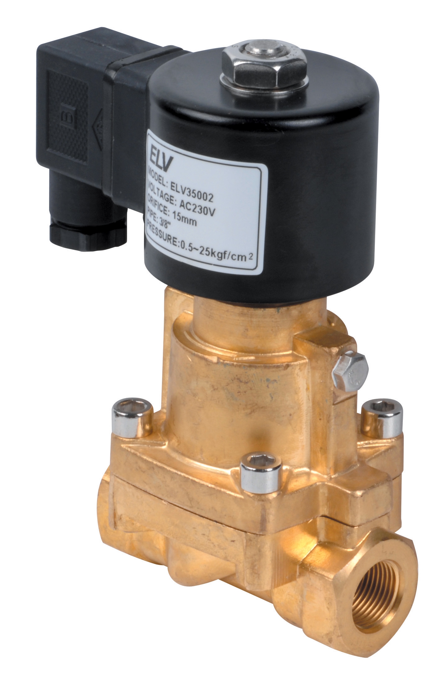
For steam and thermal applications, the ELV steam solenoid valve DN 1/2 controls steam flow across industrial heating and process systems, rated for 0.5–10 bar with 25 bar maximum differential pressure and 4.5 Cv flow coefficient, providing reliable shutoff in high-temperature applications where regular gas valves are unsuitable.
Isolation and maintenance access: Every flow control and shutoff valve must be flanked by isolation ball valves. When you need to remove a solenoid valve for cleaning or replacement, those isolation valves let you work without depressurizing the entire system.
Step 5: Design Your Monitoring and Diagnostics Strategy
A well-designed Gas Valves & Regulation system includes instrumentation that allows plant managers to diagnose issues before they become emergencies.
Pressure measurement points: Install analog pressure gauges at:
- Regulator inlet (to confirm supply pressure)
- Regulator outlet (to verify setpoint is being maintained)
- Immediately downstream of any relief valve (to detect if relief is venting)
- Before and after major restrictions or long piping runs (to quantify pressure drop)
Use glycerin-filled gauges in vibration-prone locations and ensure all gauges are rated for the maximum pressure they might see. A gauge rated for 16 bar on a 10 bar system has no margin if relief fails.
Electronic pressure transducers: In facilities with building management systems or process control networks, install 4–20 mA pressure transmitters at critical points. These integrate into SCADA systems and generate alerts if pressure deviates from setpoint beyond acceptable tolerance.
Flow monitoring: In high-consumption facilities, install a gas flow meter on the main supply line. Flow measurement helps detect system leaks early and provides data for capacity planning and energy cost allocation.
Temperature compensation: Gas regulators and pressure readings are temperature-dependent. In Singapore's tropical climate with equipment rooms reaching 40–45°C, temperature changes can shift apparent pressure by 5–10%. If precision is critical, install temperature transducers near pressure measuring points.
Step 6: Implementation and Commissioning
Once your system is designed, implementation requires discipline to prevent common failures.
Piping material: Natural gas and LPG in Singapore facilities should be distributed through seamless steel or stainless steel tubing, never copper or aluminum in areas where corrosion or chemical exposure is possible. Use flared, ferrule, or SAE connection fittings—never NPT fittings with tape. NPT fittings rely on thread deformation for sealing and are inappropriate for gas systems.
Leak detection and pressure testing: Before introducing gas, pressure-test the entire piping network at 1.5× the maximum operating pressure using dry nitrogen or air. Use a sensitive soap solution to detect leaks—even small weeps compound into significant gas loss over time. In Singapore's humid environment, use nitrogen rather than compressed air during testing; compressed air introduces moisture that promotes internal corrosion.
Regulator seating and calibration: New regulators sometimes have particles or manufacturing residue in the valve seat. Crack the outlet isolation valve open briefly to allow a small amount of gas to purge the line before fully opening. Verify the regulator is delivering its specified setpoint pressure using a calibrated test gauge, not the installed panel gauge.
Safety valve witnessing: When relief valves are installed, many facilities require a witnessing process where the relief valve is set under controlled conditions and documented. This prevents the common failure mode where relief setpoints drift over time due to vibration or corrosion.
Operator training: Train plant operators on the purpose of each component in your system. They should understand what normal pressure readings are, what changes warrant investigation, and how to safely isolate sections for maintenance.
Common Design Errors and How to Avoid Them
Error: Undersizing the primary regulator — Selecting a regulator "just enough" for current demand causes pressure droop the moment a second burner lights or demand increases. Result: fluctuating flames and incomplete combustion. Always size 20–30% above peak demand.
Error: No isolation valves — Installing a regulator without isolation valves upstream and downstream means replacing it requires shutting down the entire facility or venting all pressure to atmosphere. Budget a few hundred dollars for isolation valves; they save thousands in downtime costs.
Error: Inadequate relief protection — Assuming "the regulator won't fail" has caused explosions. Relief protection is non-negotiable. If your regulator doesn't have integrated relief, add a standalone relief valve.
Error: Ignoring thermal effects — In equipment rooms reaching 45°C in Singapore summers, gas in high-pressure systems can increase pressure 10–15% compared to morning readings at 25°C. Systems designed at cool temperatures may over-pressurize in afternoon operation. Account for seasonal and diurnal temperature variation in your relief valve setpoint.
Error: Mixing component standards — Don't specify a European-standard regulator with an American-standard solenoid valve without understanding port configurations and pressure ratings. Work with a single supplier like 3G Electric to ensure component compatibility.
Conclusion
Gas Valves & Regulation system design is as much art as engineering. It requires understanding your facility's pressure needs, selecting components that work together, and implementing monitoring that prevents surprises. By following this systematic approach—assessing requirements, selecting primary regulation, integrating safety protection, specifying shutoff control, designing diagnostics, and implementing with discipline—you create a system that operates reliably, safely, and efficiently.
3G Electric has worked with Singapore plant managers for over 35 years to build regulation systems that stand up to tropical climates, demanding operational schedules, and the regulatory environment. Whether you're designing a new system or troubleshooting an existing one, components like the Francel B25/37mb pressure regulator with integrated safety relief, the Pratissoli R1/400 regulating valve for high-pressure applications, and the Elektrogas VMM 20-25 end-of-stroke contact valve are available through our distribution network to support your system architecture.