Understanding Gas Valves & Regulation in HVAC Applications
For HVAC contractors, proper installation and calibration of Gas Valves & Regulation components represent one of the most critical aspects of system commissioning. Unlike many other industrial applications, HVAC systems demand precise pressure control across varying load conditions, with minimal tolerance for deviation. At 3G Electric, our 35+ years of experience distributing industrial equipment has shown us that 60% of field performance issues stem from improper initial setup rather than component failure.
Gas regulation in HVAC systems serves dual purposes: maintaining safe delivery pressures to burners and protecting downstream components from surge conditions. The difference between a properly calibrated regulator and one that's merely "close enough" often means the distinction between a system that operates reliably for 15 years and one requiring frequent service calls. This guide provides HVAC contractors with practical, step-by-step procedures for installation, factory calibration verification, and field testing.
Installation Best Practices and Regulator Selection
Choosing the Correct Regulator Configuration
The first critical decision involves selecting the appropriate regulator type and connection method for your specific HVAC application. Most HVAC installations fall into three categories:
Threaded Connection Systems: For smaller residential and light commercial units, threaded regulators provide compact installation options. The CBM Pressure regulator threaded D1"1/2 500 Mbar PS 5/300 Mbar accommodates systems requiring direct pipe thread connections where space constraints are significant. These units are ideal for retrofit applications and installations where minimal downtime is essential.
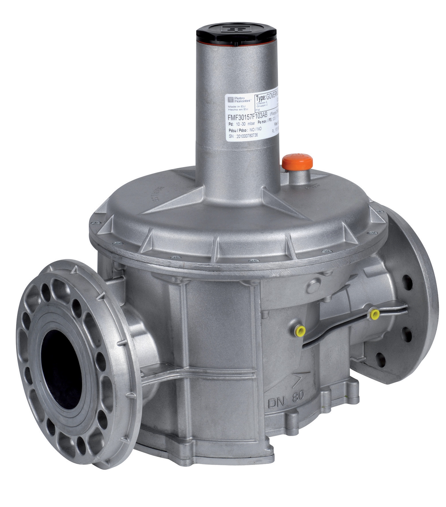
Flanged Systems for Medium Load Applications: Mid-range commercial HVAC systems typically benefit from flanged regulator configurations. The CBM Pressure regulator with flanges DN40 500 Mbar PS 5/300 Mbar provides secure, vibration-resistant connections suitable for equipment subject to thermal cycling and pressure pulsations. DN40 sizing handles most commercial building systems without oversizing components.
Large-Scale and Modular Installations: Significant commercial properties and industrial HVAC applications require the capacity and flow characteristics provided by larger flanged units. The CBM Pressure regulator with DN65 flanges 500 Mbar PS 5/300 Mbar delivers the throughput necessary for multi-zone systems while maintaining precise pressure regulation across demand variations.
Integrated Filter-Regulator Units: Modern best practices increasingly favor combined filter-regulator assemblies that eliminate separate installation steps and potential leak points. The CBM Regulator + filter DN100 500 Mbar PS 5/300 Mbar provides comprehensive gas conditioning in a single manifold, while the CBM Regulator + compact filter TAR D3/4" 500 Mbar PS 5/150 Mbar offers space-efficient solutions for compact equipment installations.
Installation Sequence and Positioning
Regulator positioning directly impacts both performance and maintenance accessibility. Follow these procedures:
- Inlet Orientation: Position inlet ports downstream of any main shutoff valves but upstream of branch distribution. Maintain minimum 12 inches of straight pipe before the regulator inlet to ensure stable pressure sensing and prevent swirling gas patterns.
- Vertical vs. Horizontal Mounting: Most HVAC regulators operate effectively in either orientation, but horizontal mounting reduces sediment accumulation in sensing passages. If vertical mounting is necessary, ensure the vent port points downward to prevent water ingress during humid conditions.
- Accessible Outlet Connection: Leave minimum 8 inches of clear space around the regulator outlet and adjustment access points. HVAC technicians must be able to connect instruments and make pressure adjustments without removing surrounding components.
- Vibration Isolation: Install regulators on vibration-damping mounts when connected to equipment with significant mechanical vibration (compressors, blowers operating above 1800 RPM). Vibration transmission causes false pressure readings and accelerates internal wear.
Pressure Calibration Procedures and Factory Setting Verification
Initial Delivery Pressure Configuration
Before final installation, every regulator must have its outlet pressure (delivery pressure) factory-calibrated to match your system specification. This critical step is often overlooked but directly determines burner performance and safety margins.
Standard HVAC Delivery Pressures:
- Natural gas burners: 3.5-4.0 inches water column (approximately 8.7-10.0 mbar)
- Propane burners: 10-12 inches water column (approximately 25-30 mbar)
- Combination systems: Dual-range regulators set to specific pressure ranges
1. With the gas supply isolated (both at meter and regulator inlet isolation valve), remove the regulator adjustment cap exposing the adjustment screw.
2. Connect a precision digital manometer to the outlet test port (if equipped) or install a tee fitting with gauge port at the outlet connection point.
3. Slowly open the inlet isolation valve, allowing gas to flow through the regulator. Do NOT open the main burner control yet—gas should flow only to the test port.
4. Observe the manometer reading. Initial setting will likely be at manufacturer default (typically 50% of maximum range).
5. Using the adjustment screw wrench (usually 5/32" or 3/16" hex), turn clockwise (increasing pressure) or counterclockwise (decreasing pressure) in quarter-turn increments.
6. Allow 30 seconds stabilization between each adjustment before recording the reading.
7. Once the manometer displays the target pressure within ±0.2 mbar, stop adjustment and verify stability over a 2-minute period.
8. Close the inlet isolation valve, disconnect the test gauge, install a blank cap on the test port, and reinstall the adjustment cap with safety seal if provided.
Factory Setting Verification for Pre-Calibrated Units
If you receive regulators pre-calibrated from 3G Electric or other suppliers, verification remains essential before system startup:
- Document the expected pressure on the unit's certification tag or box label.
- Perform the pressure measurement procedure outlined above without making adjustments.
- Acceptable variance is typically ±0.5 mbar from documented specification.
- If variance exceeds acceptable limits, do NOT place the unit in service. Contact your supplier for replacement—attempting to recalibrate pre-set units voids warranties and creates liability.
Field Testing and Commissioning Protocols
Pre-Burner Startup Gas System Verification
Before igniting burners for the first time on a new installation or after regulator replacement, execute a complete gas system integrity test:
Pressure Stability Testing:
- With the regulator isolated from burner demand (outlet isolation valve closed), monitor outlet pressure for 5 minutes using a precision manometer.
- Acceptable regulators maintain outlet pressure within ±1% of calibrated setting (less than 0.1 mbar drift for standard HVAC systems).
- Pressure drift exceeding 2% indicates internal diaphragm or seat leakage requiring component replacement.
- Establish burner demand by slowly opening the outlet isolation valve, allowing gas to flow to the main burner control (not yet calling for ignition).
- Measure outlet pressure at three distinct gas flow rates: 25% of maximum burner demand, 50%, and 100%.
- Proper regulator behavior maintains outlet pressure within ±0.3 mbar across all load points. Pressure dropping more than 0.5 mbar at maximum load indicates oversizing or internal restriction requiring investigation.
- The regulator vent port (typically located on the diaphragm cover) should emit slight gas flow proportional to outlet pressure. This is normal—the vent maintains atmospheric reference for the control diaphragm.
- If the vent emits liquid droplets, internal moisture condensation requires regulator drying or replacement. Moisture in sensing passages destroys calibration accuracy.
- If the vent emits no gas at any pressure setting, the sensing diaphragm may be ruptured. Stop service and replace the regulator immediately.
Burner Performance Commissioning
Once gas system verification is complete, initiate controlled burner ignition and observation:
1. Visual Flame Assessment: Natural gas burners should display clear, consistent blue flames with minimal yellow tips. Yellow flame tips up to 0.5 inches height are acceptable and indicate normal combustion. Extensive yellow or orange discoloration suggests oxygen deficiency (air supply restriction) or pressure inadequacy.
2. Flame Response Testing: Introduce artificial demand changes by manually adjusting the thermostat up and down through a 5-degree cycle. Flames should respond smoothly without hesitation, overshooting, or oscillation. Delayed response (more than 2 seconds) or hunting behavior (rapid cycling) indicates regulator response problems.
3. Modulating Pressure Verification: If the system includes variable-capacity burners, increase load to 75% and 100% while monitoring outlet pressure with a portable manometer connected to the outlet test port. Pressure should remain stable (±0.2 mbar) regardless of burner modulation, confirming proper regulator load compensation.
System Diagnostics and Common Field Scenarios
Pressure Instability Symptoms and Root Cause Analysis
Symptom: Outlet pressure fluctuates ±2-5 mbar or more
This condition creates flame instability, incomplete combustion, and accelerated component wear.
- Check 1 - Inlet Supply Stability: Verify inlet pressure using a manometer at the regulator inlet. If inlet pressure fluctuates, the issue originates upstream (meter oscillation, undersized inlet line, or supply side issues). Increase inlet supply line diameter or eliminate restrictions.
- Check 2 - Regulator Sizing: If inlet pressure is stable but outlet pressure oscillates, the regulator is oversized for the application. Oversized regulators oscillate because they achieve outlet pressure with minimal opening, making them unstable. Select a smaller regulator unit.
- Check 3 - Diaphragm Condition: Pressure oscillation combined with audible clicking or thumping from inside the regulator housing indicates diaphragm flutter or partial rupture. This regulator must be replaced—it cannot be field-repaired.
This typically indicates internal diaphragm seal deterioration.
- Temporary Field Procedure: Close outlet isolation valve, allow regulator to rest 10 minutes, then re-measure pressure. If pressure has recovered to the original calibrated setting, internal leakage is occurring across the control seat. The regulator is serviceable but deteriorating.
- Maintenance Decision: Slow pressure drift (0.5-1 mbar per hour) is acceptable for systems with annual maintenance and regular inspection. Rapid drift (more than 1 mbar per 10 minutes) requires replacement to prevent burner shutdown and missed comfort calls.
Integration with Filter Components
Combined filter-regulator units like the CBM Regulator + filter DN100 500 Mbar PS 5/300 Mbar and CBM Regulator + compact filter TAR D3/4" 500 Mbar PS 5/150 Mbar require coordinated maintenance:
- Filter Element Life: Inspect filter elements annually. Excessive dirt loading restricts inlet flow and creates false pressure readings. Replace elements when differential pressure across the filter exceeds 0.3 bar or annually in dusty environments.
- Dual Element Monitoring: When filter and regulator share a housing, pressure test the assembly while under load. If pressure stability improves after filter element replacement, the issue was inlet restriction, not regulator failure.
Conclusion
Proper installation, calibration, and commissioning of Gas Valves & Regulation components separates exceptional HVAC contractors from those with chronic service issues. By implementing the field procedures outlined in this guide and selecting appropriate regulator configurations from proven manufacturers, you ensure reliable system performance and reduce future service calls.
3G Electric's 35+ years of global industrial equipment distribution has demonstrated repeatedly that most HVAC system problems trace back to inadequate initial setup rather than component defects. Invest time in proper commissioning procedures, maintain detailed pressure calibration records for warranty protection, and your systems will operate reliably across their design lifespan.
For technical support selecting the appropriate regulator configuration for your specific HVAC applications or to discuss field testing procedures for complex installations, contact the 3G Electric technical team. Our expertise in gas regulation systems ensures you install systems right the first time.