Gas Valves & Regulation: Complete Maintenance & Troubleshooting Guide for Plant Managers
Managing industrial gas systems requires more than understanding basic pressure regulation—it demands practical knowledge of how gas valves and regulation systems perform under real operating conditions, how to diagnose problems before they cause downtime, and how to optimize performance while maintaining safety. Drawing on 35+ years of experience as an global industrial equipment distributor, 3G Electric has supported plant managers across multiple continents in mastering gas valves and regulation systems. This guide translates technical specifications into actionable maintenance strategies and troubleshooting protocols that directly impact your facility's uptime and safety record.
Understanding Gas Valve & Regulation System Architecture for Plant Operations
Modern industrial gas systems are integrated networks where gas valves and regulation components work interdependently. Unlike theoretical discussions of pressure control, plant managers need to understand how their specific system architecture affects day-to-day performance and failure modes.
A complete gas regulation system typically comprises three functional layers: primary regulation (reducing inlet pressure to usable ranges), secondary regulation (fine-tuning pressure for specific burners or processes), and safety components (preventing over-pressure conditions and maintaining flame stability). The relationship between these layers determines system responsiveness, stability, and safety margin.
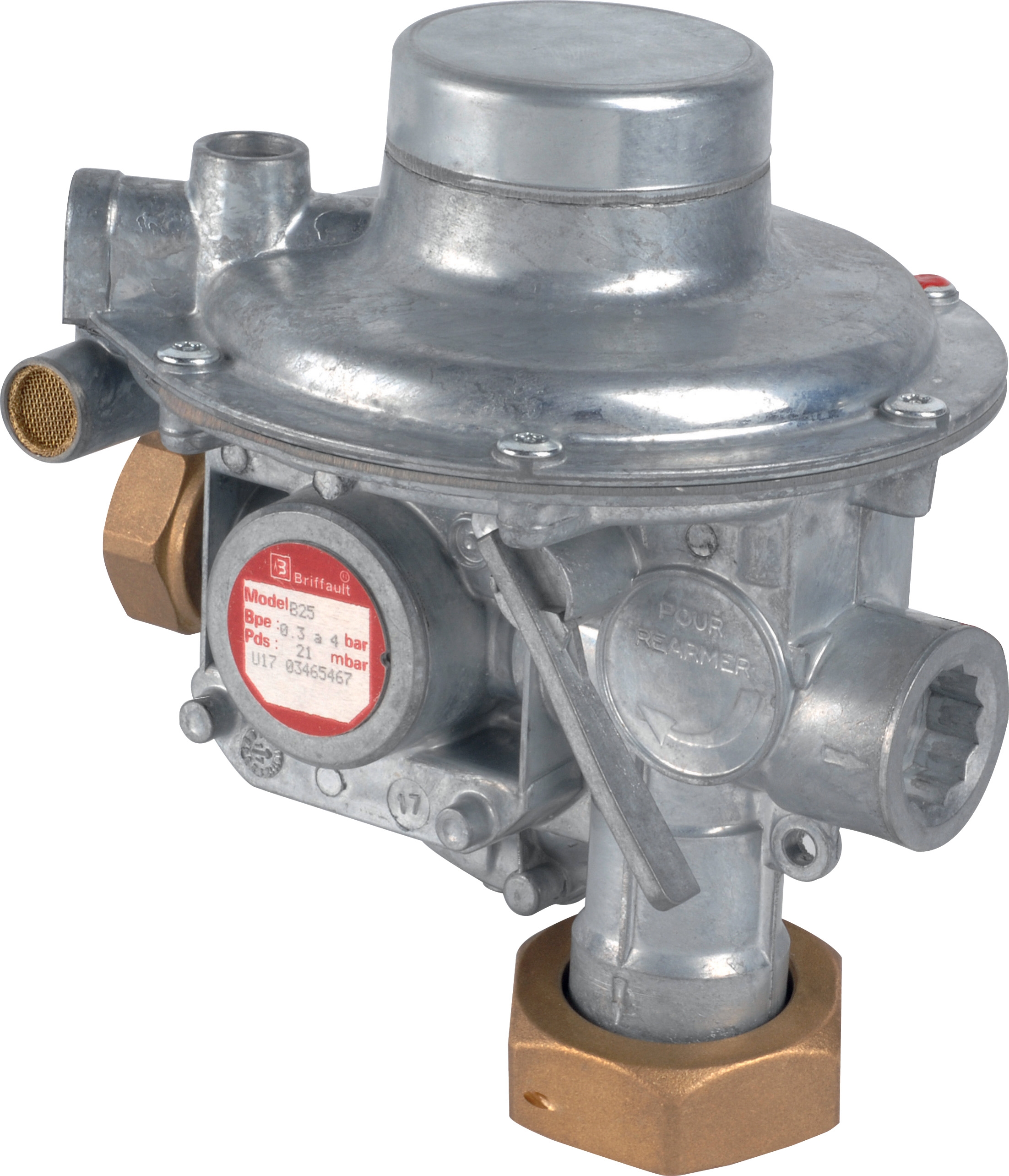
Consider the difference between a simple single-stage regulator and a two-stage system. Single-stage regulators like the CBM Pressure regulator threaded D1"1/2 500 Mbar PS 5/300 Mbar work efficiently for applications with stable inlet pressure and moderate load variation. However, when inlet pressure fluctuates significantly—common in facilities connected to municipal gas networks or operating during peak demand periods—a two-stage arrangement with primary and secondary regulators provides superior outlet pressure stability. Primary stage handles large pressure swings; secondary stage delivers the final fine-tuning with minimal deviation.
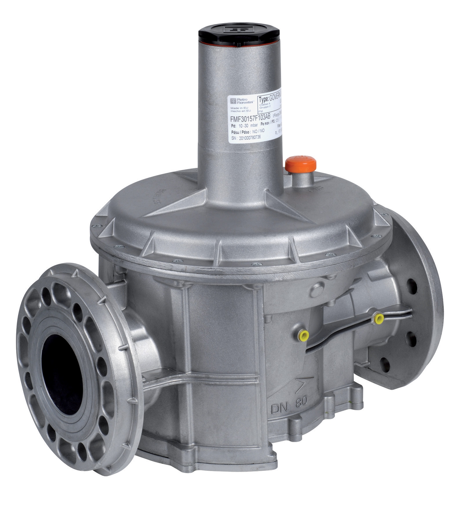
The physical configuration matters equally. Flanged regulators like the CBM Pressure regulator with flanges DN50 500 Mbar PS 5/300 Mbar and CBM Pressure regulator with DN65 flanges 500 Mbar PS 5/300 Mbar provide superior long-term reliability compared to threaded connections in high-vibration environments or installations subject to frequent service access. Flange connections distribute stress more evenly, resist loosening from thermal cycling, and simplify component replacement without breaking piping.
Diagnostic Protocols: Identifying Gas Valve & Regulation Problems Before System Failure
Plant managers who implement structured diagnostic approaches reduce unplanned downtime by 40-60%. Rather than reacting to failures, proactive diagnosis identifies developing problems during regular maintenance windows.
Pressure Stability Monitoring: The most revealing diagnostic metric is outlet pressure stability over time. Record outlet pressure readings at 15-minute intervals during normal operation for at least 8 hours. Acceptable performance shows variation of ±2-5% around setpoint depending on your process requirements. Progressive increase in deviation signals regulator deterioration—typically caused by seat wear, spring fatigue, or pilot signal contamination. Document baseline performance when equipment is new; you're looking for deviation from that baseline, not absolute numbers.
Response Time Testing: Connect a pressure gauge downstream of your regulator. Close a downstream valve rapidly (creating sudden demand reduction) and measure how long outlet pressure takes to stabilize. Sluggish response—exceeding 5-10 seconds for pressure stabilization—indicates pilot line blockage or sensitivity drift. This testing should occur quarterly on critical systems.
Inlet-Outlet Pressure Differential Analysis: Poor regulation or regulator failure typically manifests as abnormally high differential pressure. If your regulator maintains 20 bar inlet and should deliver 5 bar outlet (normal 15 bar drop), but instead shows 18-20 bar outlet pressure, the internal seat or diaphragm is likely compromised. Compare actual differentials against manufacturer specifications—these are published in datasheets and represent typical valve characteristics under normal conditions.
Audible Diagnostics: Gas regulator problems often produce characteristic sounds. A high-pitched whistling from the pilot stage indicates excessive pilot flow or worn seat geometry. Rhythmic pulsing sounds (pressure cycling) suggest the diaphragm is fatigued and can no longer maintain stable actuation. These audible signs justify immediate inspection before catastrophic failure occurs.
Temperature Monitoring at Regulator Body: Regulators dissipate energy through pressure reduction, generating measurable heat. A regulator processing high flow at large pressure differential naturally runs warmer—this is normal. However, abnormal heat concentration at one point (detected by careful hand contact after allowing safe cooling) suggests internal turbulence from seat damage or internal leakage bypassing the main valve seat and flowing through pilot vent.
Maintenance Scheduling: Extending Asset Life and Preventing Catastrophic Failures
Industrial gas regulation systems typically operate reliably for 5-10 years before major service is required. However, maintenance intervals depend on gas quality, operating pressure/flow, and installation environment.
Monthly Visual Inspections: Check for external damage, corrosion on threaded connections (indicating moisture ingress), and leakage at connection points. Verify that any pressure gauge attached to the regulator reads within expected operating range. Document readings in a maintenance log—trends matter more than individual readings.
Quarterly Filter/Strainer Verification: Most industrial installations include a strainer upstream of the regulator to prevent particulate from reaching the sensitive internal components. A blocked strainer increases inlet pressure differential and forces the regulator to work harder. Check differential pressure across the strainer; when it exceeds manufacturer specifications (typically 0.5 bar), schedule element replacement. Consider upgrading to a 10-micron or finer element if you experience recurring regulator issues—many facilities operating on lower-quality gas sources benefit from enhanced filtration.
Bi-annual Pilot System Inspection: The pilot regulating system (often a separate pilot stage or integrated pilot function) is the "brain" of pressure regulation. Inspect visible pilot connections for debris or frost (indicating moisture freeze-off). If accessible without breaking main system piping, carefully verify pilot outlet flow by momentarily blocking the vent—you should observe slight backpressure building. This confirms the pilot is responsive.
Annual Setpoint Verification: Use a calibrated test gauge to verify your regulator is still holding setpoint accurately. Document the setpoint during commissioning (this should be in your equipment file). If your regulator was set to 5 bar and now only maintains 4.7 bar, the spring is fatiguing and service is warranted within the next 6-12 months.
Major Service Intervals (3-5 Years or Per Manufacturer Schedule): At this interval, consider full regulator inspection by qualified technicians or regulator manufacturer representatives. This includes internal component examination, diaphragm integrity verification, and internal seat condition assessment. For critical applications supporting continuous processes (like industrial burners with integrated safety controls such as the CBM Regulator Francel B10/37mbar with safety), schedule this service proactively rather than waiting for failure symptoms.
Integration with Safety Systems: Gas Valves & Regulation in Burner Control Architecture
Plant managers must understand how gas regulation integrates with burner safety systems. Pressure regulators don't operate in isolation—they're part of a safety-critical control chain where failure modes can compromise facility safety.
In burner applications, the safety system architecture typically consists of: (1) main fuel shutoff valve preventing uncontrolled gas flow, (2) pressure regulator maintaining stable fuel pressure within burner design limits, (3) pilot system components ensuring reliable ignition, and (4) flame detection confirming combustion. A degrading pressure regulator that cannot maintain stable fuel pressure can trigger nuisance lockouts of your burner safety system, appearing as "intermittent flame loss" or "pressure switch faults" in your control logic.
Systems incorporating pilot lights, such as equipment controlled by the CBM 1-flame pilot light 0.150.082, depend critically on stable pilot fuel pressure. Fluctuating pressure at the pilot regulator (like the CBM Regulator Francel B10/37mbar with safety) causes pilot flame variation, reduces flame robustness, and increases likelihood of pilot extinction under draft conditions. Plant managers should verify that burner pilot pressure setpoints remain stable during your quarterly diagnostics—this single metric often predicts burner control stability months in advance.
High-capacity applications with large pressure regulators (such as the CBM Pressure regulator with DN65 flanges 500 Mbar PS 5/300 Mbar handling substantial gas flows) present different safety considerations. Failure modes include not just slow pressure drift but potential sudden vent blockage, causing uncontrolled pressure rise. These systems should include pressure relief protection downstream of the regulator, and plant managers should verify relief valve setpoint annually to ensure it provides genuine over-pressure protection.
Optimization Strategies: Improving System Performance and Energy Efficiency
Beyond maintenance and troubleshooting, plant managers can optimize gas regulation systems to improve energy efficiency and reduce operational costs.
Pressure Setpoint Optimization: Many facilities operate at historical pressure setpoints without periodically verifying they match current process requirements. Burners typically operate efficiently across a pressure range (for example, 5-12 bar rather than requiring exactly 8 bar). Operating at the minimum pressure necessary for reliable combustion reduces fuel-air mixing energy and can reduce gas consumption by 2-5% while improving flame stability. Work with your burner manufacturer to identify your safe minimum operating pressure, then adjust secondary regulator setpoint accordingly.
Regulator Sizing Matching: Undersized regulators (too small for your flow requirement) operate at maximum capacity, reducing responsiveness and increasing pressure drop. Oversized regulators (handling flows well below their capacity) show excessive hysteresis and poor control sensitivity. Review your typical operating flow against your regulator's flow capacity rating. If your application shows significant flow variation (peak demand double your average demand), a two-stage regulation system with the primary regulator sized for peak demand and secondary regulator sized for average demand provides superior control.
Installation Environment Improvements: Gas regulator performance depends partly on ambient conditions. Regulators exposed to direct sunlight experience temperature swings that affect internal spring characteristics and diaphragm response. Shielding regulators from direct solar radiation or installing them in insulated enclosures stabilizes performance. In cold climates, water vapor in incoming gas can freeze in the pilot line, causing stiction or blockage. Installing a liquid-trap separator upstream of the regulator prevents this failure mode.
Key Takeaways for Plant Managers
- System architecture matters: Single-stage vs. two-stage regulation, and threaded vs. flanged connections all affect real-world performance and reliability. Match your system configuration to your pressure stability requirements and installation environment.
- Structured diagnostics prevent failures: Implement monthly visual checks, quarterly performance monitoring, and annual setpoint verification. Documenting trends reveals developing problems before they cause unplanned downtime.
- Maintenance intervals depend on operating conditions: High gas quality, stable inlet pressure, and lower operating flows extend service intervals. Plan major regulator service every 3-5 years unless diagnostics indicate earlier intervention is needed.
- Integrate regulation with safety systems: Pressure regulator health directly affects burner control stability, pilot reliability, and flame safety. Include regulator diagnostics in your burner safety system verification procedures.
- Optimization opportunities exist: Verify that your pressure setpoints match current process requirements. Consider two-stage systems for applications with variable loads. Address installation environment factors like temperature extremes and moisture exposure.
Contact 3G Electric for Gas Valves & Regulation Support
With 35+ years of experience as an experienced global distributor, 3G Electric supports plant managers across multiple industries in selecting, installing, and maintaining gas valves and regulation equipment. Whether you need regulator replacement, system optimization consultation, or technical troubleshooting support, our team brings field experience across diverse industrial applications and operating environments.
We stock a comprehensive range of pressure regulators including the threaded CBM Pressure regulator threaded D1"1/2 500 Mbar PS 5/300 Mbar, flanged models like the CBM Pressure regulator with flanges DN50 500 Mbar PS 5/300 Mbar and CBM Pressure regulator with DN65 flanges 500 Mbar PS 5/300 Mbar, specialized safety regulators such as the CBM Regulator Francel B10/37mbar with safety, and pilot light components like the CBM 1-flame pilot light 0.150.082. Contact our technical team to discuss your specific gas valve and regulation requirements—we'll help you optimize performance, extend equipment life, and maintain the safety standards your facility demands.