Understanding Controls & Safety System Architecture for Diagnostics
Controls & Safety systems in industrial burners operate as integrated circuits with multiple fail-safe pathways. Before troubleshooting, maintenance teams must understand the hierarchical architecture: sensor inputs (flame detection, pressure monitoring), processing logic (relay controllers, safety interlocks), and output controls (solenoid valves, ignition commands). Each component serves a specific diagnostic entry point.
When a Controls & Safety failure occurs, the system typically fails safe—shutting down combustion rather than continuing with degraded safety margins. This design philosophy is critical: a non-responsive system is safer than a partially responsive one. The challenge for maintenance teams is distinguishing between legitimate safety shutdowns (preventing dangerous conditions) and nuisance shutdowns (component degradation without actual hazard).
With 35+ years of experience distributing industrial burner controls, 3G Electric has observed that approximately 70% of Controls & Safety failures originate not from the primary control component itself, but from supporting elements: corroded sensor connections, contaminated flame detection windows, fouled pressure sensing lines, or inadequate power supply regulation. Understanding this distribution shapes your diagnostic methodology—always verify system infrastructure before replacing high-cost control modules.
Systematic Field Diagnostic Procedures
Phase 1: Pre-Test Documentation and Safety Verification
Before conducting any diagnostics, establish baseline conditions. Document the failure signature: exact timing of shutdown, ambient conditions, recent maintenance activities, fuel type and pressure, and flame signal characteristics if visible. This contextual information eliminates 40% of misdiagnoses immediately.
Verify isolation procedures. Controls & Safety circuits must be de-energized during diagnostic work, with appropriate lockout-tagout protocols implemented. Test the power supply voltage at the burner control terminals—not at the breaker panel. Voltage drop between the panel and control module can mask inadequate supply conditions. Specification: most electronic Controls & Safety controllers (such as Brahma Relay CE 191.4 TW30/TS10) require stable 230V ±10% input. Measure actual voltage under full load conditions.
Phase 2: Sensor Signal Verification
Flame Detection Testing: This is the most critical diagnostic point. The flame detector generates the signal authorizing fuel delivery. Measure flame signal strength at the ionization input of the control module using a high-impedance DC voltmeter or dedicated flame signal probe (minimum 10 MΩ input impedance). Expected ionization current ranges from 1.2 to 5 µA depending on burner size and fuel type.
If signal is absent or too weak:
- Clean the flame detection electrode visually—carbon deposits reduce conductivity dramatically
- Inspect the electrode insulation for cracks; ceramic or stainless steel electrodes like CBM Stainless Steel Electrode L.1m 2013347 can fracture under thermal stress
- Check electrode positioning relative to flame: typically 8-12mm from flame envelope for optimal signal
- Verify grounding path—measure continuity between electrode body and burner frame ground
If signal is present but control still shuts down: the problem lies in signal processing, not detection. Proceed to Phase 3.
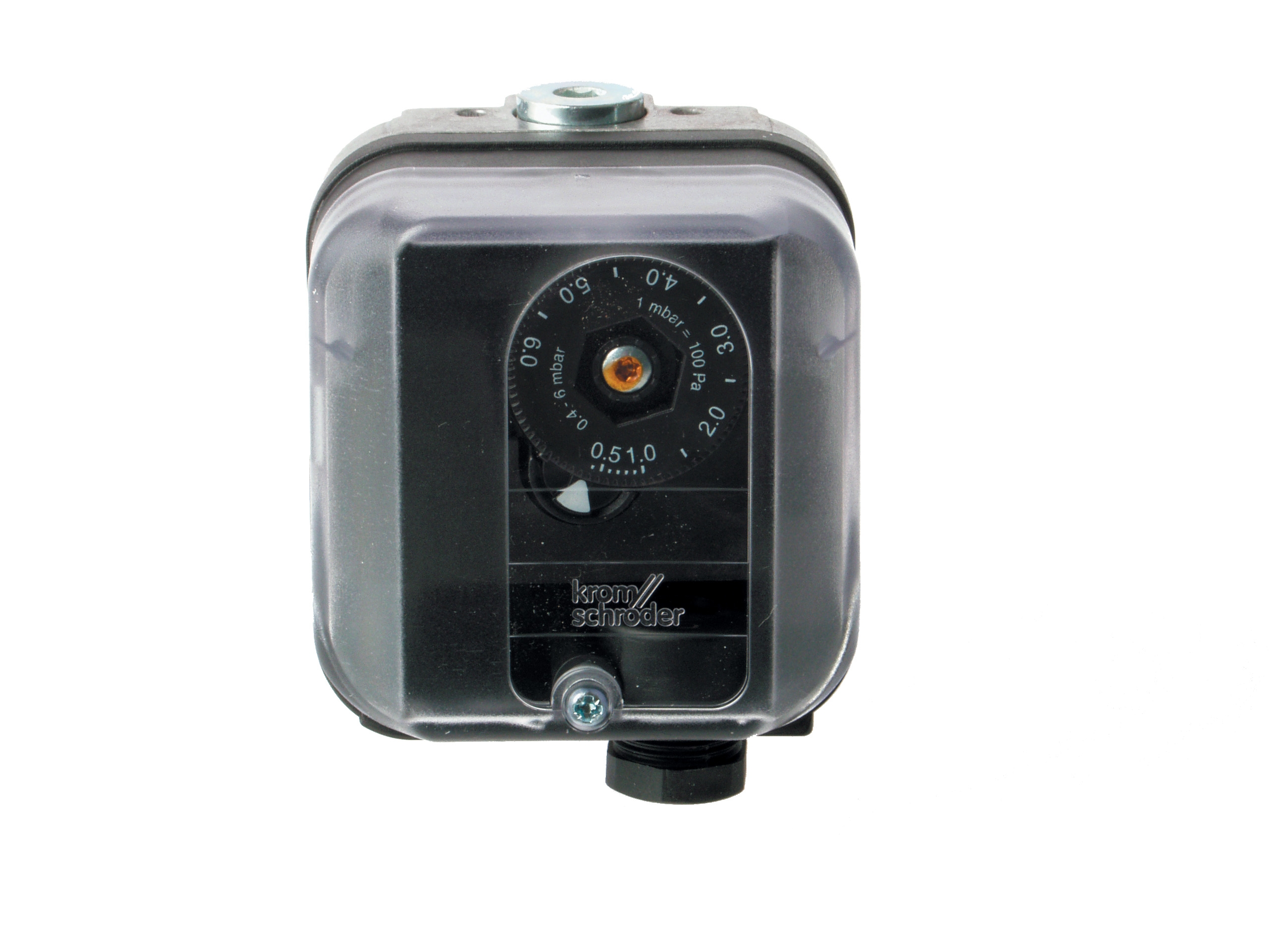
Pressure Switch Testing: Pressure switches like Kromschroder DG 50U/6 control fuel delivery authorization and monitor operating safety margins. Testing requires accurate gauge placement—measure fuel pressure at the pressure switch port, not downstream. Pressure switches have mechanical switching points: the switch closes (authorizes fuel) at a setpoint and opens (cuts fuel) at a reset point typically 0.5-1.0 bar below setpoint.
Test procedure:
1. Disconnect the pressure switch electrical connector
2. Isolate the burner with the fuel isolation valve closed
3. Slowly increase system pressure using the fuel pump
4. Listen for the audible "click" indicating switch closure
5. Record this pressure—it should match the manufacturer's setpoint (±0.2 bar tolerance)
6. Continue increasing pressure and note the reset point
7. Cycle pressure up and down three times to verify consistent operation
If the switch fails to click at any point or clicks inconsistently, replacement is required. The SIL 3 rating of switches like the DG 50U/6 depends on precise mechanical operation; hysteresis or stiction is not acceptable in safety-critical circuits.
Phase 3: Control Module Logic Testing
Electronic Controls & Safety modules contain safety interlocks that may appear as failures but are actually protecting the system. Test the logic sequence:
Purge Cycle: Most controls implement a mandatory purge (blower running, no fuel) before ignition. This purges combustion air through the burner to prevent explosive gas accumulation. If the burner won't ignite after 20-30 seconds of blower runtime, the purge timer or interlock may be stuck. Measure blower contactor voltage—it should energize within 5 seconds of power-up.
Ignition Enable: After purge, the control permits fuel and ignition simultaneously. If flame is not detected within 3-5 seconds, the control shuts down and requires manual reset (on older models) or automatic retry. Measure ignition transformer output during this window—typically 8-12kV AC for spark electrodes. Missing output indicates transformer failure or control module output failure.
Flame Establishment: Once flame signal appears, the control typically maintains fuel for a proving period (2-10 seconds) before stabilizing to running state. If the control locks out after brief flame appearance, the flame signal is insufficient or intermittent. Return to Phase 2 sensor verification.
Use a Siemens Cell QRB4A-B036B40B flame detector as a reference point—this UV cell-type detector provides extremely fast response (100ms typical) and high immunity to false signals. If your current flame detection is unreliable, consider upgrading to cell-type detection rather than electrode-based systems.
Interlock Verification: SIL-rated controls implement multiple interlocks. Test these in sequence:
- Reset interlock: The reset button should require manual action; no automatic restart on power restoration
- Fuel isolation interlock: Closing the fuel isolation valve should halt combustion within 2-3 seconds
- High-limit thermostat interlock: If present, triggering the thermostat should stop fuel flow immediately
Phase 4: Power Supply and Wiring Assessment
Power quality issues are invisible but persistent causes of Controls & Safety failures. Use a power quality analyzer to measure:
- Voltage stability (should remain within ±10% of nominal)
- Harmonic distortion (THD should not exceed 5% on burner circuits)
- Voltage sag events (momentary dips that trigger nuisance shutdowns)
- Ground continuity (< 1 ohm resistance from any metal burner component to ground)
Wiring contamination is equally critical. High-voltage ignition circuits and low-level flame signal circuits must be physically separated and shielded. Measure insulation resistance on all control wiring using a 500V megohm meter: all circuits should show > 1 MΩ resistance to ground. Values below 100 kΩ indicate moisture ingress or contamination requiring rewiring.
For relay-based controls like Brahma Relay CE 191.4 TW30/TS10, verify relay coil voltage at the relay terminals during operation—not at the control panel. Coil voltage must be within 85-110% of rated voltage. Sustained low voltage indicates inadequate power supply capacity.
Practical Repair Strategies and Component Replacement
When to Replace vs. Repair
Electronic control modules (solid-state or relay-based) cannot be repaired in the field and must be replaced as complete units. However, supporting components often can be restored:
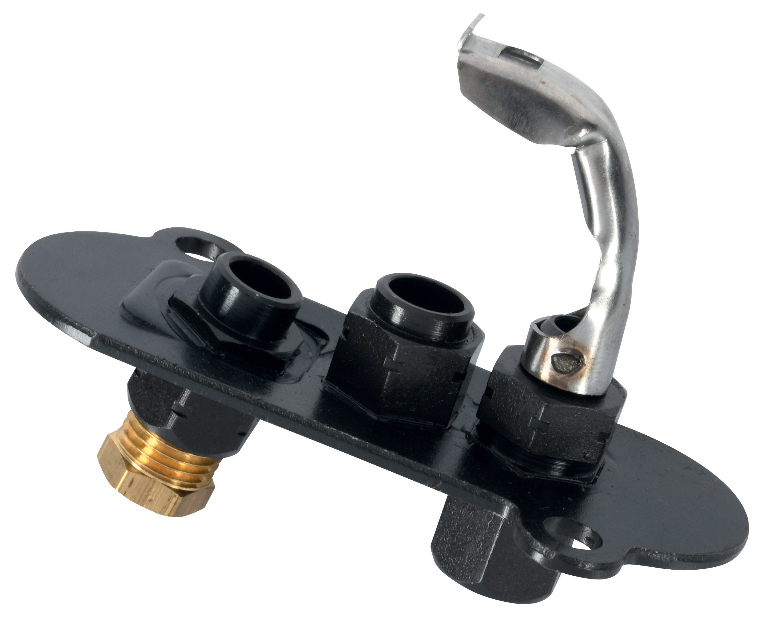
Pilot Lights: Devices like Sit Universal Pilot Light 2 Flames 3 Positions serve critical functions in manual-shutdown systems. Before replacement, verify:
- Gas supply pressure at pilot inlet: typically 5-10 mbar above main burner pressure
- Igniter condition: the aluminium oxide element should glow orange within 10 seconds of ignition
- Pilot flame position: the flame must contact the thermocouple or flame detection electrode
- Air shutter adjustment: excess air cools the pilot; deficient air causes carbon accumulation
Many "failed" pilot lights are actually fuel-starved or misadjusted. Restore operation before scheduling replacement.
Electrodes: Corroded or cracked flame detection electrodes degrade over time and eventually fail. Stainless steel electrodes like the CBM 900mm electrode rated to 600°C represent the upgrade path from carbon steel. Their superior corrosion resistance extends life 3-5x. Replacement is justified when:
- Visual inspection shows hairline cracks in ceramic insulation
- Cleaning no longer restores signal strength
- Resistance measurement shows > 10 MΩ instead of specified 3 MΩ
- Setpoint has drifted > 0.3 bar despite adjustment attempts
- Reset point shows hysteresis > 1.0 bar
- Switch fails to operate consistently over three pressure cycles
- Visual inspection reveals corrosion on diaphragm housing
Commissioning After Component Replacement
After replacing any Controls & Safety component, execute a full functional test:
1. Static Tests (power off):
- Verify all wiring connections match original schematic
- Measure insulation resistance on all circuits
- Check mechanical operation of fuel isolation valve and reset button
2. Dynamic Tests (power on, no fuel):
- Confirm purge cycle operates for specified duration
- Verify reset interlock prevents restart without manual action
- Check high-voltage outputs with oscilloscope (if equipped)
3. Dynamic Tests (power on, fuel available):
- Confirm ignition occurs within 5 seconds of purge completion
- Verify flame signal strength during operation
- Test pressure switch operation at actual operating point
- Simulate fuel isolation—combustion should stop within 3 seconds
4. Safety Interlock Tests:
- Trigger reset button multiple times—each should stop combustion and require manual restart
- If equipped with high-limit thermostat, trigger it—combustion should stop immediately
- Test fuel isolation valve manual closure—combustion should stop within 3 seconds
Document all test results. This creates a baseline for future diagnostics and proves that system safety functions operate as designed.
Preventive Maintenance to Extend Controls & Safety Life
Controls & Safety system reliability improves dramatically with systematic preventive maintenance. Based on 35+ years of field observations, implement these intervals:
Monthly: Visual inspection of flame detection windows and electrode surfaces. Carbon deposits reduce flame signal 30-50%. Ten minutes of cleaning extends component life significantly.
Quarterly: Pressure switch operation test as described in Phase 2. Verify setpoint accuracy. Replace pressure gauge if accuracy is uncertain (gauges drift 1-2% annually).
Annually: Full functional test sequence as described above. Measure insulation resistance on all wiring. Clean air intake filters that supply combustion air—restricted air increases carbon deposits on flame detectors.
Biennial: Replace any mechanical electrodes showing visual wear; upgrade to stainless steel equivalents during replacement. Recalibrate any adjustable setpoints using calibrated reference instruments.
This preventive approach reduces emergency troubleshooting by 60-70% and extends average component life from 10 years to 15+ years—a significant cost advantage despite modest preventive maintenance investment.