Introduction: Controls & Safety System Reliability Through Preventive Diagnostics
Industrial burner Controls & Safety systems represent critical infrastructure in heating applications across manufacturing, chemical processing, and district heating facilities. Unlike reactive maintenance approaches, preventive diagnostics allow maintenance teams to identify degradation before failures occur. With over 35 years of experience distributing industrial control equipment, 3G Electric has supported maintenance teams globally in developing robust testing protocols that maximize equipment uptime while maintaining safety compliance.
This guide provides maintenance teams with structured procedures for testing and maintaining the core components of burner control systems: control relays, solenoid valves, flame detectors, and associated wiring. By implementing these diagnostic protocols on a scheduled basis, your facility can achieve significant reductions in unplanned downtime and safety incidents.
Section 1: Control Relay Testing and Functional Verification
Understanding Relay Operating Principles
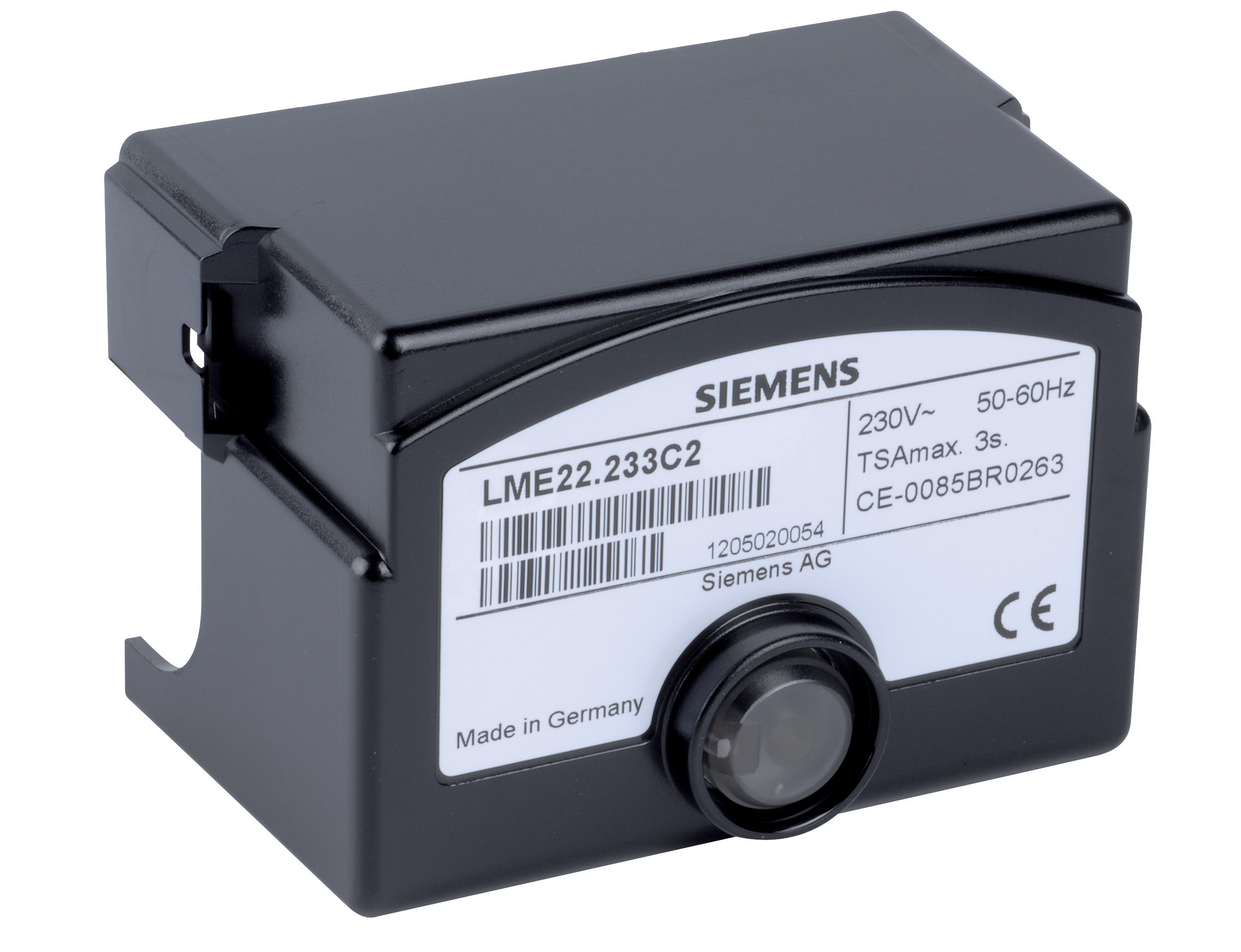
Burner control relays serve as the intelligence layer of your Controls & Safety system. Models like the Satronic Relay DMG 970-N MOD.01 and Siemens LME 22 233C2 relay continuously monitor flame detection signals and coordinate ignition sequences. These relays operate by energizing coils that mechanically switch high-voltage contacts—any degradation in coil response time or contact resistance directly compromises safety functionality.
Preventive Testing Protocol for Control Relays
Visual Inspection Phase:
- Remove relay from its mount and inspect for burn marks, discoloration, or corrosion on terminals
- Check for accumulated dust or debris around coil windings
- Verify terminal connections are tight (resistance should not exceed 0.1 ohms)
- Examine switch contacts for pitting, wear, or oxidation
- Using a digital multimeter set to ohms, test coil resistance according to manufacturer specifications (typically 500–3000 ohms for burner relays)
- Measure contact resistance when relay is de-energized (should read 0.2–0.5 ohms)
- Energize the relay and verify contacts switch cleanly with minimal arcing
- Document baseline measurements for trend analysis
- Manually apply supply voltage while monitoring response with an oscilloscope or relay test set
- Verify pickup voltage occurs within manufacturer tolerance (typically 85–110% of rated voltage)
- Measure dropout voltage (should be 10–15% below rated voltage)
- Confirm switching time falls within specification limits (usually 10–50 milliseconds)
- Document that flame signal dropout triggers immediate relay de-energization
- Connect a test load (100W resistive load minimum) to relay contact terminals
- Apply supply voltage and verify contacts hold load without chattering
- Cycle relay 10 times while monitoring for contact bounce or welding
- If any abnormality appears, relay must be replaced immediately
For systems using Sit Control box Sit 0579311, perform the same tests plus verification of the 25 Hz repetition rate using a frequency counter—this ignition rate ensures spark gap consistency during pilot light establishment.
Troubleshooting Degraded Relays
When testing reveals slow response times (>100ms pickup), weak contact resistance (>1.5 ohms), or voltage tolerance drift beyond ±15%, the relay has reached end-of-service life. Coil insulation breakdown accelerates exponentially once initial degradation appears; replacement is safer and more economical than attempting repair.
Section 2: Solenoid Valve Response and Seal Integrity Testing
Solenoid Valve Operating Characteristics
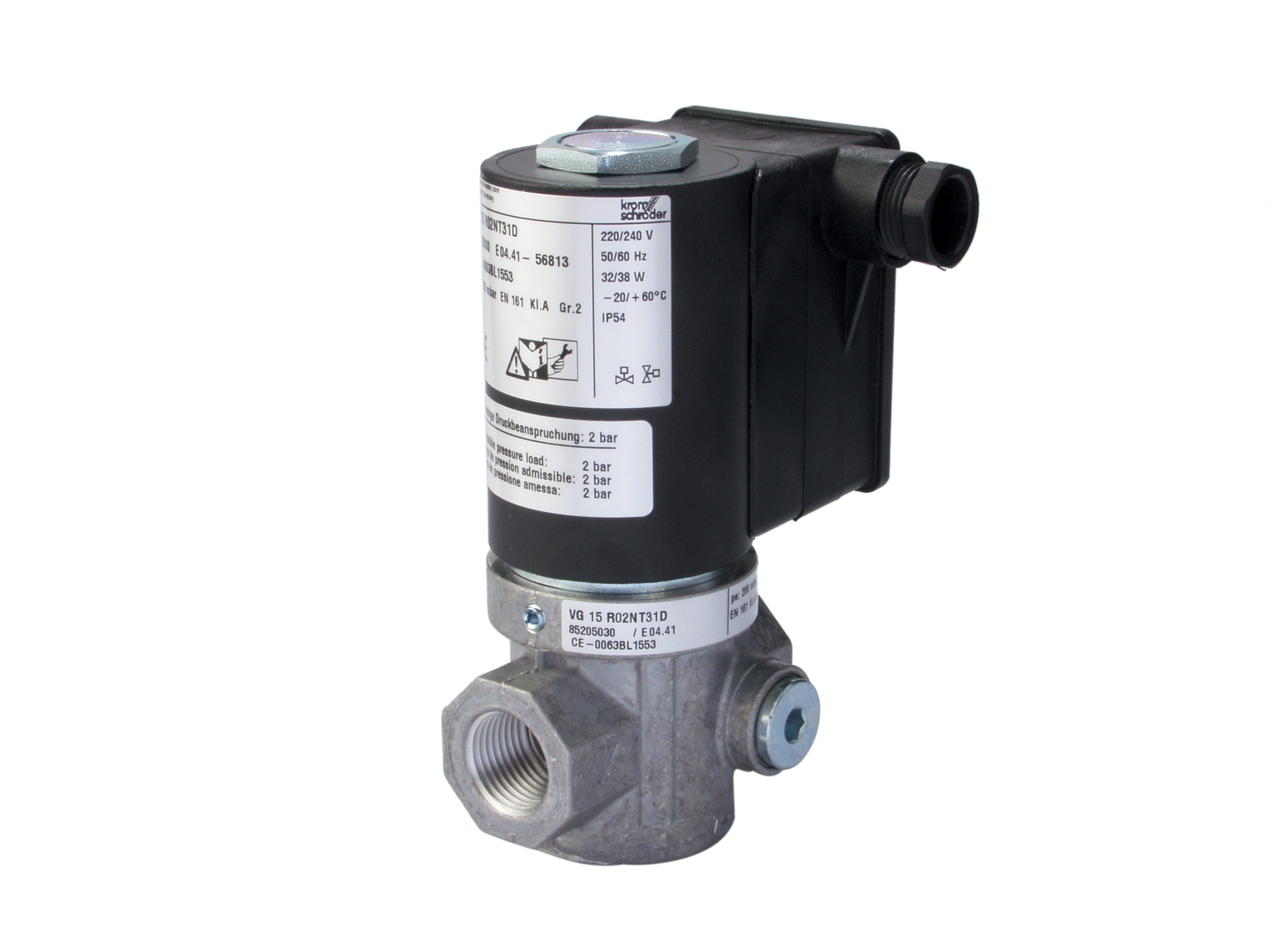
Rapid-response solenoid valves like the Kromschroder Fast gas solenoid valve VAS 115R/NQ control gas flow during burner ignition and operation. These devices must respond predictably within milliseconds while maintaining absolute seal integrity under operating pressure. Response time degradation or internal leakage directly impacts burner safety by delaying fuel shutoff during alarm conditions.
Functional Testing Procedures
Electrical Circuit Verification:
- Measure coil resistance with multimeter (Kromschroder VAS series typically 400–600 ohms for 230V coils)
- Verify coil voltage matches system supply (±10% tolerance)
- Test coil insulation resistance using insulation tester at 500V DC (should exceed 10 megaohms)
- Confirm proper polarity on DC solenoids; incorrect polarity creates arcing and coil failure
- Use solenoid valve test equipment with pressure transducers to measure opening delay
- Record time from electrical command to detectable pressure change at outlet
- Typical fast-response gas solenoids should respond within 50–150 milliseconds
- Slower response times indicate coil winding degradation or sticking plunger
- Compare measurements to baseline data from initial commissioning
- Close isolation ball valves isolating the solenoid from active system
- Pressurize test chamber to 80% of maximum rated pressure using test pump
- Apply regulated nitrogen gas (never pressurize with burner fuel)
- Listen carefully for internal leakage at outlet port using stethoscope
- Check downstream pressure gauge for pressure rise (indicates leakage past main poppet)
- Internal leakage exceeding 10 mL/min at rated pressure requires solenoid replacement
- De-energize solenoid and carefully remove coil assembly (note shim stack configuration)
- Manually lift plunger to verify smooth travel without sticking or gritty feeling
- Apply light oil (ISO VG 32) if plunger moves with excessive friction
- Reassemble with identical shim configuration; incorrect shim stack creates stiction and poor response
Pressure Drop Calculation
Before returning solenoid to service, calculate system pressure drop across the valve at expected flow rate. For gas applications, maximum pressure drop should not exceed 50 mbar at normal operating flow. Higher pressure drop indicates partially blocked valve seat or degraded seal—both reasons for replacement.
Section 3: Flame Detection Circuit Diagnostics
Flame Detector Types and Signal Characteristics
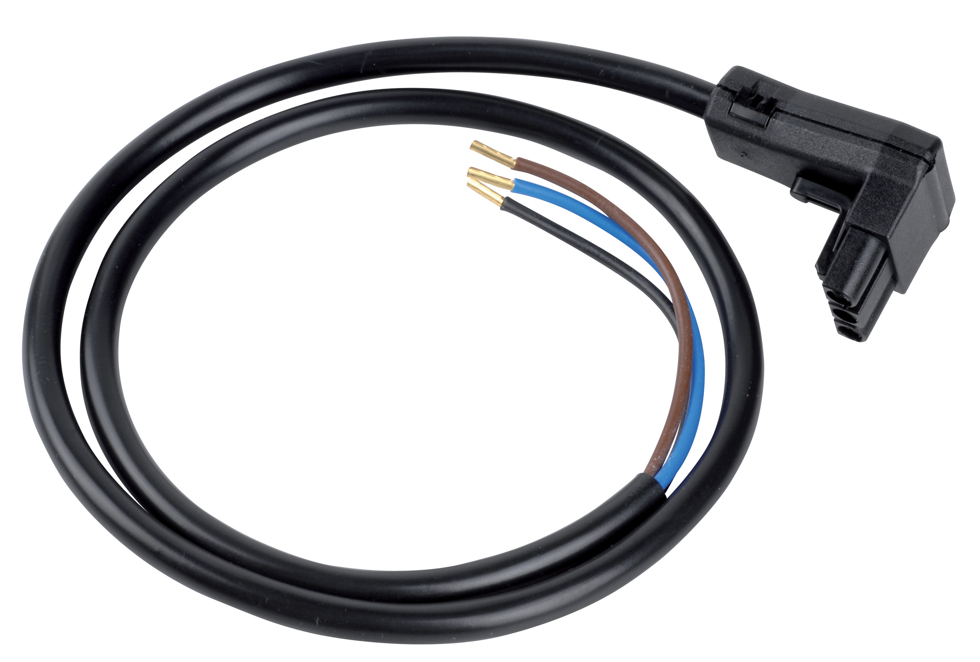
Modern industrial burners employ two flame detection technologies: ultraviolet (UV) sensors like the Satronic Cable for cell IRD10 and infrared (IR) detectors. Both generate weak electrical signals (typically 1–5 microamps for UV, variable voltage for IR) that must be amplified and interpreted by control relays. Any degradation in detector optics, cable insulation, or connector integrity cascades into false flame signals or failure to detect actual flame.
Flame Detector Optical Testing
UV Detector Maintenance:
- Power down burner system and cool to ambient temperature
- Remove detector from burner housing using care to avoid mechanical shock
- Inspect quartz window for soot accumulation, moisture, or crazing
- Clean window using soft cloth dampened with deionized water—never use solvents
- Allow window to air dry completely before reinstallation
- Verify detector mounting is secure and aimed directly into flame path
- Reconnect detector to control system with burner offline
- Energize burner to establish pilot flame (or use manufacturer's UV test lamp)
- Measure detector output signal using sensitive microammeter: UV detectors typically produce 2–4 microamps in flame
- Signal below 1.5 microamps indicates dirty optics or sensor degradation requiring replacement
- Document baseline signal strength for future trending
- Visually inspect flame detector cables for cracking, brittleness, or heat damage
- Check connectors for corrosion, loose pins, or water ingress
- Measure cable insulation resistance between conductor and shield: should exceed 100 megaohms at 500V DC
- Apply gentle tension to connectors—any movement or crackling sounds indicates poor contact requiring recrimping or replacement
- For Satronic cables, verify 4-pole connection integrity and 950 nm spectral response band
IR Detector Signal Quality Assessment
Optical Path Verification:
- Inspect IR detector lens for dust, condensation, or discoloration
- Clean lens carefully using optical cleaning tissue and isopropyl alcohol
- Verify detector mounting allows unobstructed view of flame core
- Check that flame shield or deflector does not restrict IR radiation path
- Connect analog voltmeter to detector output while burner operates
- Measure output voltage in flame (typically 3–8V DC depending on detector model)
- Monitor voltage stability over 60-second observation period—acceptable variation is ±0.5V
- Voltage drift, oscillation, or sudden drops indicate failing optical coupling or photodiode degradation
- Off-flame signal should measure <0.5V DC; anything higher suggests stray light interference
- During normal burner operation, transmit high-frequency RF energy near detector using portable RF generator (FM radio at high volume placed nearby)
- Observe control system—detector should maintain stable signal without fluctuation
- If detector signal varies with RF field, shielding is inadequate and cable must be routed away from high-voltage wiring or replaced with better-shielded variant
Section 4: Scheduled Maintenance and Documentation Systems
Establishing Preventive Testing Intervals
Optimal maintenance frequency depends on hours of operation, fuel type, and ambient conditions. As a baseline:
- Monthly visual inspections: Relay condition, cable integrity, connector corrosion
- Quarterly functional testing: Complete relay timing tests, solenoid response measurements, flame signal verification
- Semi-annual deep diagnostics: Full electrical and mechanical testing of all components with trend analysis
- Annual replacement: Filter elements in pressure switches, thermal cutout devices, and UV detector windows
Industrial burners operating continuously or in corrosive environments (coastal facilities, chemical plants) require more frequent intervals. Seasonal burners can extend intervals during idle periods.
Creating Baseline and Trend Data
Effective preventive maintenance relies on understanding how your specific equipment performs when new. Develop baseline data sheets for each control system component:
Critical Baseline Parameters:
- Control relay coil resistance (ohms)
- Relay pickup and dropout voltages (% of rated voltage)
- Relay switching time (milliseconds)
- Solenoid coil resistance (ohms)
- Solenoid response time (milliseconds)
- Solenoid internal leakage (mL/min at rated pressure)
- Flame detector signal strength in flame (microamps or volts)
- Flame detector signal stability (voltage variance over 60 seconds)
- Cable insulation resistance (megaohms)
- All terminal connection resistances (ohms)
Record these values on initial commissioning or immediately after component replacement. Plot measurements on control charts to identify trends. When any parameter degrades 20% from baseline, schedule component replacement before failure occurs.
Maintenance Documentation and Compliance
Maintain detailed records for each burner control system:
- Testing procedure used and test equipment calibration dates
- Measurement results with photographs of test setup
- Any repairs, adjustments, or component replacements performed
- Date and technician name for full traceability
- Any deviations from specification with remedial actions taken
This documentation supports regulatory compliance audits, liability protection, and knowledge transfer to new maintenance staff. For facilities operating under ISO 50001 or similar standards, documented preventive maintenance directly contributes to energy efficiency and safety certifications.
Component Sourcing and Spare Inventory
When maintenance testing identifies components requiring replacement, 3G Electric maintains inventory of burner control relays, solenoid valves, and detector cables compatible with systems from Satronic, Siemens, Sit, Kromschroder, and other major manufacturers. Maintaining spare inventory of high-wear components—solenoid coils, relay contact assemblies, flame detector cables—reduces emergency downtime when failures occur.
Conclusion
Systematic preventive maintenance and diagnostic testing transform Controls & Safety systems from reactive failure management to proactive reliability engineering. By implementing the procedures outlined in this guide, maintenance teams achieve measurable improvements in equipment availability, safety performance, and operational cost management. 3G Electric's 35+ years of experience supporting industrial maintenance operations has demonstrated that facilities investing in structured preventive diagnostics reduce burner-related safety incidents by 60–70% while extending component service life by 3–5 years beyond industry norms.
Begin implementation by selecting your highest-criticality burner system and establishing baseline measurements for all key parameters. Expand the program systematically across your facility, documenting results consistently. Within 12 months, your team will have accumulated sufficient trend data to optimize testing intervals and spare parts inventory specific to your operational environment.