Understanding Controls & Safety Through Temperature Management
Controls & Safety in industrial burner systems extends far beyond flame detection and solenoid valve sequencing. Temperature sensing and thermostat-based load regulation represent a critical—and often overlooked—layer of process safety that protects equipment from thermal stress, improves fuel efficiency, and prevents cascade failures. With over 35 years of experience distributing industrial equipment, 3G Electric has observed that many plant managers underestimate the role thermostats play in comprehensive safety architecture.
Temperature control operates as both a safety mechanism and an operational efficiency tool. When a burner system overshoots setpoint temperature, it doesn't just waste fuel—it can trigger secondary safety interlocks, stress heat exchanger materials, and create dangerous pressure conditions downstream. Modern industrial facilities require thermostats that integrate seamlessly with control logic, provide repeatable accuracy, and offer adjustable differential bands to prevent rapid cycling that degrades equipment and safety systems alike.
Thermostat Architecture and Safety Integration
Industrial thermostats function as boundary controllers between the combustion process and downstream safety interlocks. Unlike simple on-off switches, precision thermostats provide changeover contact arrangements that allow simultaneous control of fuel supply, air dampers, and alarm circuits.
Single-Pole Changeover Contact Design:
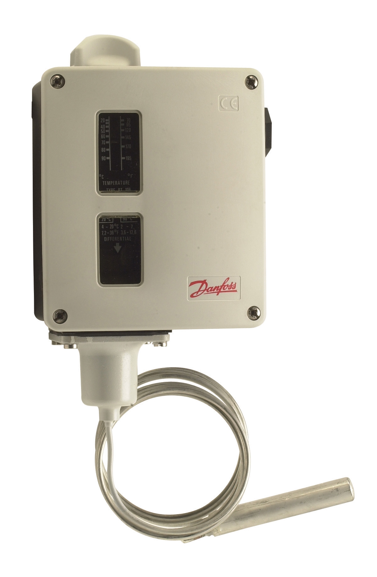
The Danfoss RT 107 exemplifies modern thermostat architecture with its universal single-pole changeover contact. This design enables plant managers to configure multiple control functions from one device: fuel supply modulation on temperature rise, air intake management on setpoint deviation, and auxiliary alarm activation when thermal conditions exceed safe ranges. The changeover configuration means one thermostat can simultaneously break a primary heating circuit while closing a secondary cooling or bypass circuit—essential for applications where overshoot carries operational or safety risk.
Adjustable Differential and Neutral Zone:
The Danfoss RT 124 extends thermostat capability by offering adjustable differential settings with optional neutral zone functionality. The differential—the temperature band between ON and OFF states—prevents rapid switching that causes:
- Premature valve wear and solenoid coil fatigue
- Pressure surge conditions that trigger relief valves
- Temperature oscillation that confuses downstream interlock logic
- Increased maintenance costs and unplanned downtime
Neutral zone capability adds a "dead band" between heating and cooling setpoints, critical for systems that must maintain temperature within narrow ranges without triggering both heating and cooling circuits simultaneously. This feature prevents the destabilizing effect of simultaneous heat input and heat rejection.
Practical Load Management: Preventing Thermal Overshoot
Thermal overshoot occurs when burner input exceeds the setpoint, causing equipment stress and potential safety chain activation. Plant managers must understand the relationship between thermostat response time, flame detector cycling, and downstream pressure control.
Load Ramp and Setpoint Management:
In HVAC and process heating applications, thermostats with 2-3°C differential settings prevent excessive cycling while maintaining setpoint accuracy. However, aggressive differential reduction without corresponding burner modulation can cause overshoot if the burner cannot reduce flame quickly enough. This is where Pactrol CSS01 housing control modules become critical—they integrate the thermostat signal with actual flame relay feedback and timed sequencing to ensure the burner stages down proportionally as temperature approaches setpoint.
Consider a 100 kW heating system serving a process vessel:
1. Thermostat detects approach to setpoint (e.g., 85°C rising toward 88°C setpoint)
2. Control module receives signal and begins reducing fuel supply through pilot/main flame staging
3. Flame detector continuously monitors actual combustion state to confirm fuel reduction
4. Temperature rise decelerates as input falls below load demand
5. System achieves stable operation at or near setpoint without cycling or overshoot
Without integrated thermostat-to-control-module logic, the system either cycles excessively or overshoots, both of which compromise safety and efficiency.
Response Time Considerations:
Bulb-actuated thermostats like the Danfoss RT 124 sense temperature through a remote bulb element, introducing a slight response delay. In high-mass systems (large heat exchangers, heavy piping), this delay is negligible and actually beneficial—it prevents over-correction. In fast-response systems (thin-walled heat exchangers, direct-contact heating), plant managers may need to specify tighter differential bands or consider electronic temperature transmitters that feed proportional signals to modulating control valves.
Thermostat Integration with Flame Detection Safety Systems
A thermostat cannot function in isolation. Its output must coordinate with the flame detection chain to prevent fuel delivery when the burner cannot sustain combustion.
The Control Sequence:
The Honeywell Cell C 7044 A 1006 ultraviolet flame detector continuously monitors flame presence. If flame is lost while the thermostat is demanding heat:
1. Flame detector output drops immediately
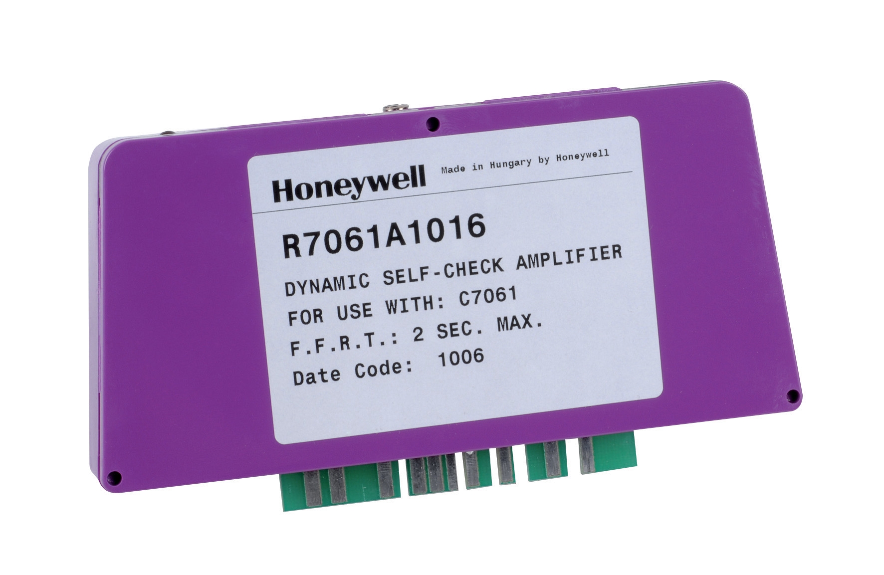
2. Honeywell Amplifier R 7861 A 1026 processes the loss-of-flame signal
3. Control module closes fuel solenoid valve within 1-2 seconds
4. Thermostat demand remains active but cannot reestablish fuel supply until flame is confirmed
5. Burner enters lockout, requiring manual reset or automatic retry cycle
This cascade ensures that thermostat demand alone cannot override flame loss protection—a critical safety principle. Some industrial facilities mistakenly assume thermostats are "secondary" controls and prioritize flame detection systems. In fact, both must cooperate: flame detection provides instantaneous response to combustion failure; thermostats provide sustained load matching and prevent thermal conditions that could damage the flame detector or cause pressure relief activation.
Commissioning and Field Verification for Plant Managers
When installing or commissioning thermostat-based control systems, plant managers should verify:
1. Differential Band Accuracy:
Activate the burner and allow temperature to rise from cold. Record the exact temperature at which the thermostat switches OFF (upper setpoint). Allow the system to cool and record the temperature at which it switches back ON (lower setpoint). The difference should match the specified differential. If differential is wider than expected, overshoot risk increases; if narrower, cycling frequency increases.
2. Neutral Zone Function (if applicable):
For systems with both heating and cooling circuits, verify that activating the heating thermostat does not simultaneously activate cooling. The neutral zone should prevent overlapping operation. Test by raising setpoint; cooling should remain inactive. Lower setpoint; heating should remain inactive. Only when setpoint crosses into a defined range should one circuit activate.
3. Interlock Coordination:
With the burner running at temperature, manually interrupt the thermostat signal (disconnect or block bulb sensing element). The control module should reduce fuel supply within 2-3 seconds, and the flame detector should confirm flame reduction. This verifies that the thermostat signal is genuinely controlling the combustion process, not just cycling a pilot light.
4. Response Time Under Load:
Operate the system at 80% of typical load and measure the time from setpoint approach to burner modulation. This real-world response time—typically 10-30 seconds for bulb-actuated thermostats—ensures the system can handle load transients without excessive overshoot.
Maintenance and Long-Term Reliability
Thermostat bulbs and sensing elements degrade over time due to thermal cycling and vibration. 3G Electric's 35+ years in industrial distribution have shown that thermostat maintenance is among the most cost-effective preventive measures:
- Annual inspection: Check bulb for corrosion, cracks, or loose connections. Ensure capillary tubing is intact and not kinked.
- Calibration verification: Every 2-3 years, compare thermostat actuation temperature to a calibrated reference thermometer. Acceptable drift is typically ±2°C.
- Cleaning: Dust and scale on the bulb surface reduce thermal response. Clean gently with a soft cloth; do not use solvents that might compromise the bulb seal.
- Replacement scheduling: Budget for thermostat replacement every 5-7 years in high-cycling applications, or every 10 years in stable load conditions.
The cost of a replacement thermostat (typically €50-150) is negligible compared to the cost of a boiler overshoot causing a pressure relief discharge or a control system malfunction due to degraded sensor accuracy.