Controls & Safety: Selecting Sensors and Amplifiers for Southeast Asian HVAC Applications
For HVAC contractors operating across Southeast Asia, Controls & Safety systems must contend with unique environmental challenges—high humidity, temperature extremes, and tropical weather patterns—that demand careful component selection. With 3G Electric's 35+ years of experience as a global equipment distributor, we've worked with thousands of contractors installing burner control systems in this demanding region. The difference between a reliable installation and premature failure often comes down to understanding how flame detectors, amplifiers, and thermostats perform in real-world field conditions.
This guide focuses on the practical aspects of selecting and integrating flame detection sensors and temperature control devices for HVAC systems operating in Southeast Asia. Rather than generic theory, you'll find actionable insights based on field experience and environmental realities contractors face daily.
Section 1: Understanding Flame Detection Requirements in Tropical Environments
Why Flame Detector Selection Matters
Flame detection is the cornerstone of burner safety. A flame detector continuously monitors the presence of flame during operation; if the flame is lost, the control system triggers an immediate shutdown sequence within milliseconds. This is non-negotiable for safety compliance across Singapore, Malaysia, Thailand, and other Southeast Asian markets.
In Southeast Asia, contractors must account for several environmental factors that directly impact flame detector performance:
- High Ambient Temperatures: Outdoor installations and mechanical rooms frequently exceed 40°C. Ultraviolet (UV) flame detectors are more temperature-sensitive than infrared alternatives, and extended exposure to heat reduces their operational lifespan.
- Humidity and Moisture Ingress: The region's tropical climate creates condensation challenges. Poorly sealed detector housings lead to internal corrosion and false signals.
- Dust and Particulate Matter: Industrial sites and urban areas introduce airborne contaminants that can coat optical elements, reducing signal clarity.
- Electrical Interference: High-density electrical installations in modern buildings generate electromagnetic noise that can trigger false flame signals if amplifiers lack proper filtering.
The Honeywell Cell C 7044 A 1006 ultraviolet flame detector is widely specified for gas and oil burner applications across the region. Its 1-inch tube design fits standard mounting locations, and its UV sensing approach works reliably in most Southeast Asian installations. However, contractors must ensure that the mounting location minimizes direct sunlight exposure and provides adequate protection from moisture ingress—common installation oversights that lead to callback problems.
Amplifier Performance in High-Vibration Environments
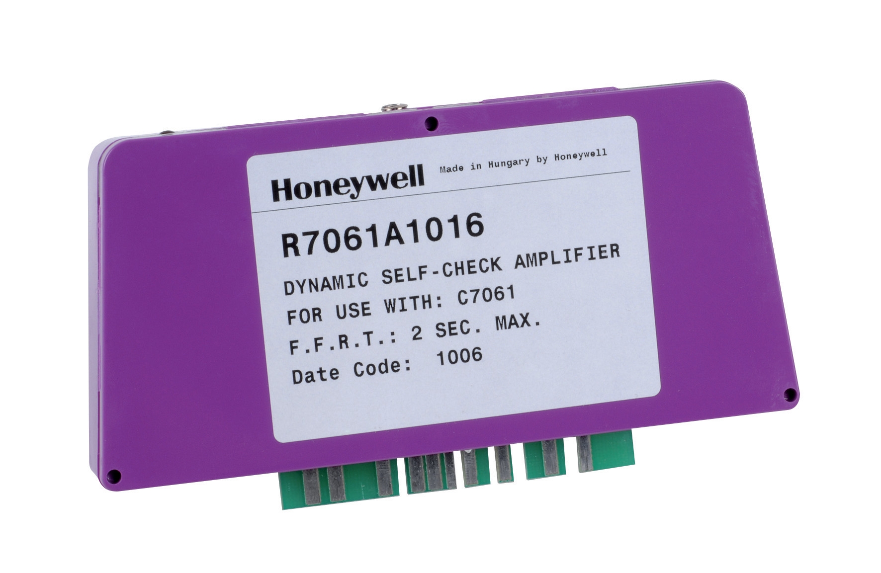
Flame detectors don't operate in isolation. The amplifier—the electronic control module that processes the detector signal—must be equally robust. The Honeywell Amplifier R 7861 A 1026 is specified for burner control systems with demanding vibration tolerance ratings. Its -40°C to 60°C operating range and 0.5 g continuous vibration tolerance make it suitable for Southeast Asian industrial environments where equipment may be subject to pumps, compressors, and other mechanical equipment operating nearby.
Key performance considerations for amplifiers in your region:
- Response Time: Most modern amplifiers have response times under 100 milliseconds. Verify this specification when selecting components—slower responses can miss rapid flame fluctuations common in some burner types.
- Sensitivity Adjustments: Southeast Asian contractors often need to adjust amplifier sensitivity to account for optical obstruction from dust or steam. Ensure the amplifier includes trim potentiometer or software adjustment capabilities.
- Power Supply Stability: Inconsistent electrical supply in some locations requires amplifiers with robust input voltage filtering. Verify input voltage tolerance ratings (typically 24 V ±10% or similar).
Section 2: Temperature Control and Thermostat Selection for Climate Diversity
Matching Thermostat Type to Application
Temperature control in HVAC systems begins with selecting the correct thermostat design. Southeast Asian contractors work with two primary thermostat architectures: bulb-actuated (mechanical) and electronic control devices.
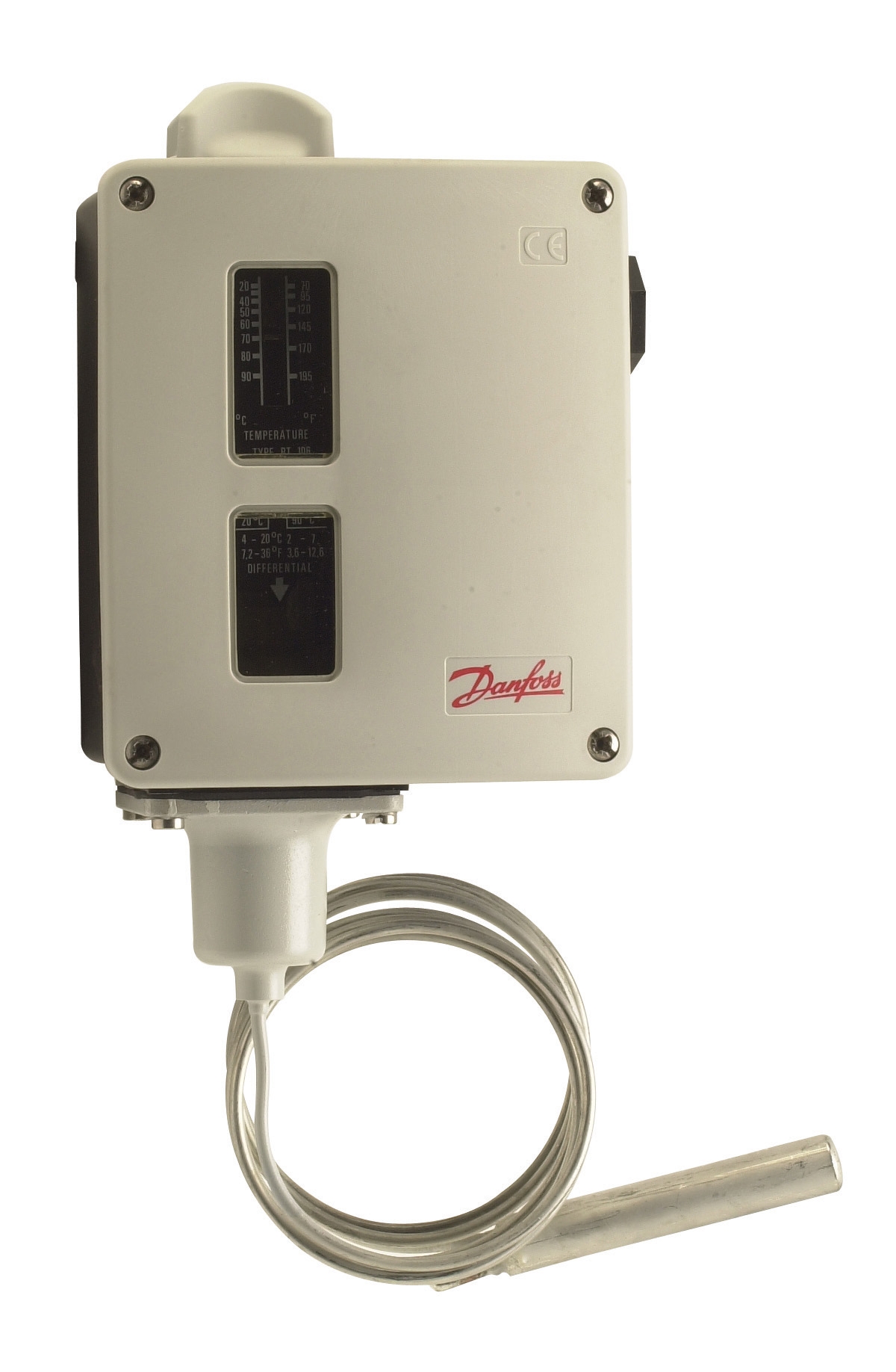
The Danfoss Thermostat RT 124 is a bulb-actuated thermostat with adjustable differential and optional neutral zone—features that directly address the operational challenges of the region.
When to specify bulb-actuated thermostats:
- Applications without reliable electrical power backup (rural installations, areas with frequent outages)
- Systems requiring simple, single-stage temperature control
- Process applications where the system operates continuously but requires overshoot prevention
- Installations where electrical noise or interference makes electronic sensing problematic
The RT 124's adjustable differential setting is particularly valuable in Southeast Asia. In tropical climates, rapid ambient temperature swings between day and night create hunting problems (frequent on-off cycling) if the differential is too narrow. A broader differential—typically 3-5°C in this climate—reduces thermal cycling and extends burner life.
Alternatively, the Danfoss Thermostat RT 107 offers a universal single-pole changeover contact design suitable for smaller heating applications and backup system configurations. Its compact design fits retrofit installations where space is limited.
Integrating Thermostat and Flame Detection
A common installation error occurs when contractors overlook the interaction between temperature control and flame detection circuits. The thermostat initiates the burner (via interlock relay), but the flame detector monitors actual flame presence. Both must operate in coordinated sequence:
1. Thermostat closes its contact → burner ignition sequence begins
2. Flame detector senses flame → amplifier confirms ignition to control module
3. System operates in burner-on state → thermostat maintains contact as long as temperature is below setpoint
4. Temperature reaches setpoint → thermostat opens contact → ignition sequence stops, solenoid valve closes, flame extinguishes
This sequence must complete within defined timeframes. If the thermostat's contact takes too long to close (mechanical hystericty), or if the flame detector's response is sluggish, timing mismatches cause hard starts or false flame loss signals.
In Southeast Asia, where maintenance intervals are sometimes longer than recommended, specify thermostats with accessible mechanical components. The Danfoss RT 107 and RT 124 models feature design-in accessibility that simplifies field calibration and replacement.
Section 3: Practical Integration of Burner Control Modules
Understanding Multi-Functional Control Modules
The Pactrol CSS01 12 housing control module represents the integrated approach to burner controls—combining timed relay, flame relay, and electronic spark generator functions in a single package. For contractors in Southeast Asia, this integration strategy offers significant advantages:
- Reduced Wiring Complexity: Fewer external components mean fewer connection points prone to corrosion or poor contact, a critical consideration in humid climates.
- Coordinated Timing: All ignition and safety functions operate on synchronized timing logic, eliminating the possibility of sequencing errors that occur when separate relays are manually coordinated.
- Thermal Protection: A well-designed integrated module includes built-in temperature compensation, so ignition timing and flame response remain consistent across the 30-50°C ambient temperature swings typical in Southeast Asian facilities.
The Pactrol CSS01 housing is rated for atmospheric and small forced-air burners up to 60 kW—suitable for most commercial HVAC applications in the region (residential and small commercial). Its timed relay function ensures that the spark ignition system operates only during the startup sequence, preventing unnecessary electrode wear and arcing.
Installation Best Practices for Tropical Conditions
When integrating the control module, thermostat, flame detector, and amplifier, follow these Southeast Asia-specific practices:
Enclosure Placement and Protection
- Install control modules in weatherproof, IP54-rated or higher enclosures. Avoid mounting on exterior walls where salt spray or monsoon water ingress is possible.
- Orient enclosure vents downward to prevent standing water accumulation.
- Maintain minimum 15 cm clearance around the enclosure for ventilation. In high-ambient environments (>40°C), consider forced-air cooling or thermally-shielded enclosures.
- Use marine-grade stainless steel or nickel-plated terminals. Standard copper terminals oxidize rapidly in humid conditions, creating high-resistance connections that degrade signal quality.
- Seal all external cable entries with silicone grommet or epoxy-based sealant. Water wicking along control cables is a common failure mode in monsoon seasons.
- Maintain voltage drop under 3% across all control circuits. Southeast Asian sites often have extended runs to burner systems; use larger gauge wire than standard recommendations if distances exceed 50 meters.
- Position the UV detector (like the Honeywell Cell C 7044) to view the primary flame but avoid direct view of the ignition electrode during spark-only phases. Stray ignition UV can false-trigger the detector.
- Mount the detector at least 30 cm from the burner head to avoid radiant heat exposure from surrounding components.
- Use a stainless steel or ceramic detector tube adapter if the original mounting has aluminum components. Dissimilar metal corrosion is accelerated in tropical humidity.
- Mount the thermostat sensor bulb in flowing air, away from radiant heat sources and direct solar exposure. In Southeast Asia, morning sun on control enclosure exteriors can cause sensor drift of 2-3°C, triggering false alarms.
- Ensure 10+ cm spacing from burner exhaust outlets to prevent hot air recirculation around the sensor bulb.
- For installations with outdoor air intake, specify thermostats with narrow-band thermal lag characteristics. Rapid ambient shifts between heated indoor air and outside air create overshooting if thermostat response is too slow.
Section 4: Commissioning and Field Verification
Safety-Critical Testing Sequence
After installation, a structured commissioning sequence ensures all Controls & Safety functions operate correctly:
1. Flame Detector Verification: With the system in manual test mode, introduce a small flame (match or lighter) within the detector's field of view. The amplifier should respond (typically, an LED illuminates) within 1-2 seconds. If response is sluggish or inconsistent, the detector may have optical contamination—clean the lens carefully with lens paper and isopropyl alcohol.
2. Amplifier Response Test: Verify that the amplifier cuts off ignition and closes the fuel solenoid within the system's safety shutdown window (typically 3-5 seconds). Simulate a flame loss by blocking the detector's view; the system should transition to safe shutdown.
3. Thermostat Continuity Check: With the system off, measure resistance across the thermostat's contact at room temperature. It should read < 1 Ω (nearly zero). Cycle the thermostat setpoint above and below ambient, confirming the contact opens and closes at expected temperatures.
4. Interlock Coordination: In full operation, confirm that the thermostat's contact closure initiates the burner sequence, the flame detector responds within the safety window, and no false shutdowns occur during 30 minutes of continuous operation.
Maintenance and Recalibration Intervals
For Southeast Asian installations, establish quarterly maintenance schedules (twice the standard interval) to account for higher environmental stress:
- Thermostat Calibration: Every 6 months, verify the setpoint accuracy using a calibrated thermometer. Mechanical thermostats can drift 1-2°C annually in high-humidity environments.
- Flame Detector Optical Cleaning: Inspect every 3 months; clean if dust accumulation is visible on the optical window. A moderately contaminated detector can reduce signal strength by 30-40%, causing delayed response times.
- Amplifier Potentiometer Check: If the system has encountered multiple false flame loss events, measure amplifier sensitivity using the specified test procedure and compare to commissioning baseline. Readjust if drift exceeds ±10%.
- Connection Torque Verification: On an annual basis, re-torque all terminal connections using a calibrated torque wrench. Vibration and thermal cycling loosen connections that were tight at installation.
Key Takeaways for Southeast Asian HVAC Contractors
With 3G Electric's 35+ years of global equipment distribution experience, we've seen that successful HVAC installations in Southeast Asia depend on three factors: selecting components rated for tropical conditions, understanding how environmental factors degrade performance, and committing to rigorous commissioning and maintenance sequences.
The components referenced in this guide—the Honeywell Cell C 7044 A 1006 detector, Honeywell Amplifier R 7861 A 1026, Danfoss RT 124 and Danfoss RT 107 thermostats, and Pactrol CSS01 12 control module—represent field-proven selections that have delivered reliable performance across Singapore, Malaysia, Thailand, and beyond. However, the best equipment can fail without proper installation practices tailored to local climate and site conditions.
Use this guide as a reference during design, installation, and commissioning phases. When in doubt about component interactions or site-specific challenges, consult with 3G Electric's technical team—our experience across thousands of Southeast Asian installations can help you avoid costly callbacks and ensure safety compliance.