Understanding Controls & Safety Integration Architecture
Controls & Safety in modern industrial burner systems depends on the seamless integration of three critical component classes: temperature sensors, flame detectors, and signal amplifiers. Rather than operating independently, these devices form an interconnected control loop where each element depends on the others for reliable system operation.
For maintenance teams in Southeast Asia managing aging industrial infrastructure, understanding this integration is essential. Over 35 years of experience as a distributor of industrial equipment, 3G Electric has supported facilities across the region in optimizing these control architectures. The challenge lies not just in selecting individual components, but in ensuring they communicate correctly, respond within specified timeframes, and fail safely when conditions warrant shutdown.
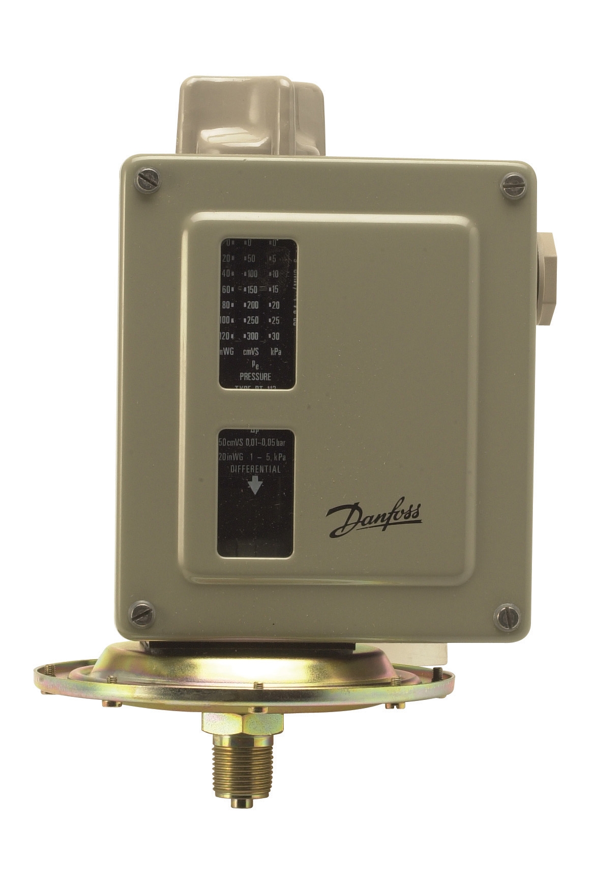
The Danfoss Thermostat RT 124 serves as the temperature sensing layer in this architecture. This bulb-actuated thermostat maintains setpoint control with adjustable differential and neutral zone capability—critical for preventing thermal cycling that degrades burner efficiency and component lifespan. The thermostat's single-pole changeover contact initiates control signals that cascade through the system.
Flame detection occurs via the Honeywell Cell C 7044 A 1006, an ultraviolet detector designed specifically for gas and oil burner applications. This 1-inch tube-mounted sensor continuously monitors combustion status, generating a low-voltage signal that feeds directly to amplification circuits.
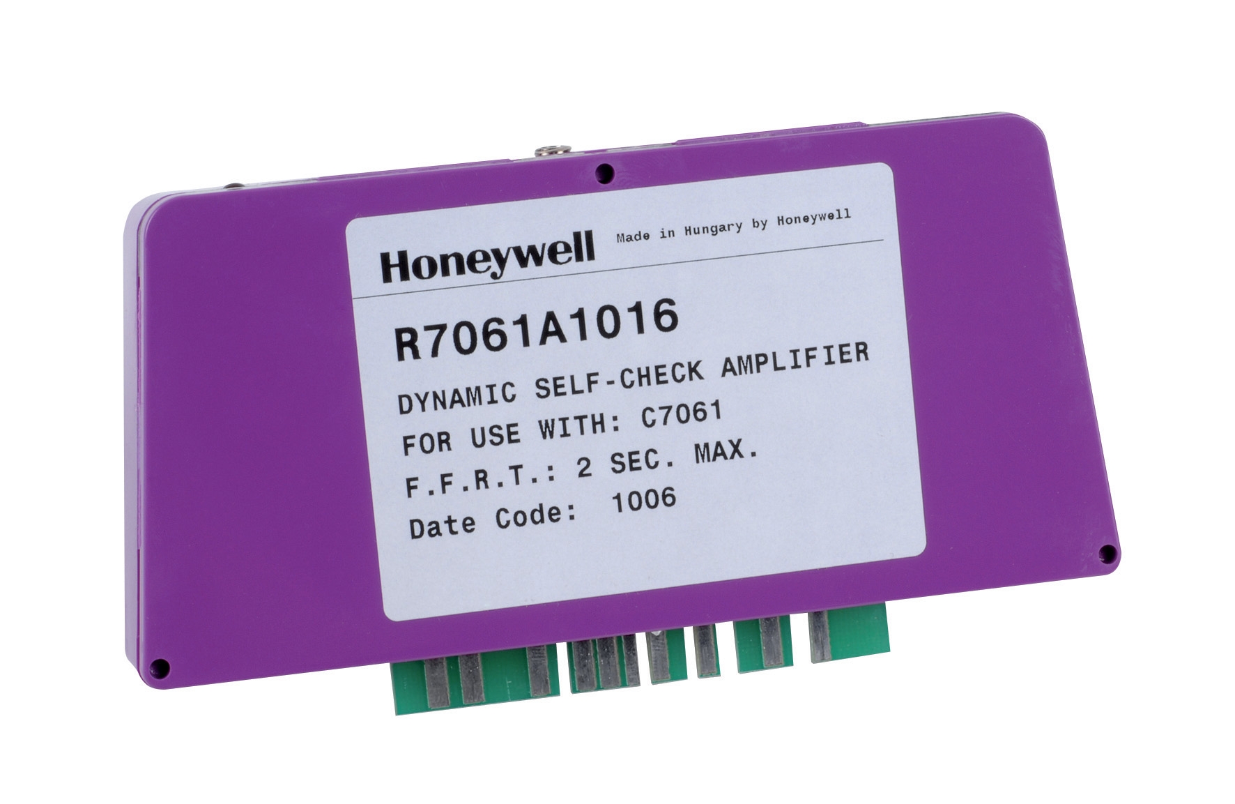
The signal amplification layer—represented by the Honeywell Amplifier R 7861 A 1026—conditions the flame detector signal into logic-level outputs suitable for relay coils and solenoid valve control circuits. This amplifier operates across -40°C to 60°C, a critical specification for Southeast Asian facilities where equipment rooms may lack climate control.
Component Interaction and Electrical Sequencing
Maintenance teams must understand the electrical sequencing that occurs when these components interact. The thermostat does not directly control the burner—it initiates a control sequence. The sequence typically follows this pathway:
Thermostat Contact Closure → Control Module/Relay Logic → Flame Detector Monitoring → Amplifier Output → Solenoid Valve and Burner Ignition
The Pactrol CSS01 12 housing control module integrates these signals into a unified control architecture. For burners up to 60 kW, this module combines a timed relay (manages pre-purge and post-purge cycles), flame relay (sustains burner operation during flame-on condition), and electronic spark generator (ignition function).
What distinguishes this architecture from simpler on-off controls is the temporal separation of functions. The control module enforces a mandatory sequence:
1. Pre-purge phase: Fan motor runs without ignition, clearing combustion chamber of unburned fuel. Duration typically 10-30 seconds.
2. Ignition phase: Spark generator energizes while fuel gas solenoid opens. Ignition window typically 4-8 seconds.
3. Flame detection confirmation: UV detector must sense flame within ignition window. If detection fails, system de-energizes solenoid and locks out.
4. Run phase: Thermostat maintains burner operation. Flame detection monitors continuously; loss of flame triggers immediate shutdown.
5. Post-purge phase: After thermostat setpoint satisfaction, fan runs without fuel for 5-15 seconds before complete shutdown.
For maintenance teams, the critical insight is this: a thermostat cannot be isolated from its flame detector. If the thermostat initiates the sequence but the flame detector fails to confirm combustion, the burner shuts down, regardless of thermostat position. This interdependency prevents unsafe operation—a controlled failure mode—but requires integrated troubleshooting.
Commissioning and Field Validation Protocols
When installing or replacing thermostat-amplifier-detector systems, maintenance teams must follow systematic commissioning steps. These procedures validate component interaction before the system operates under full load.
Pre-Commissioning Verification
Before energizing the control circuit:
- Verify thermostat bulb placement in the process stream. For steam applications, use immersion wells; for air/gas applications, place bulb in the discharge airflow.
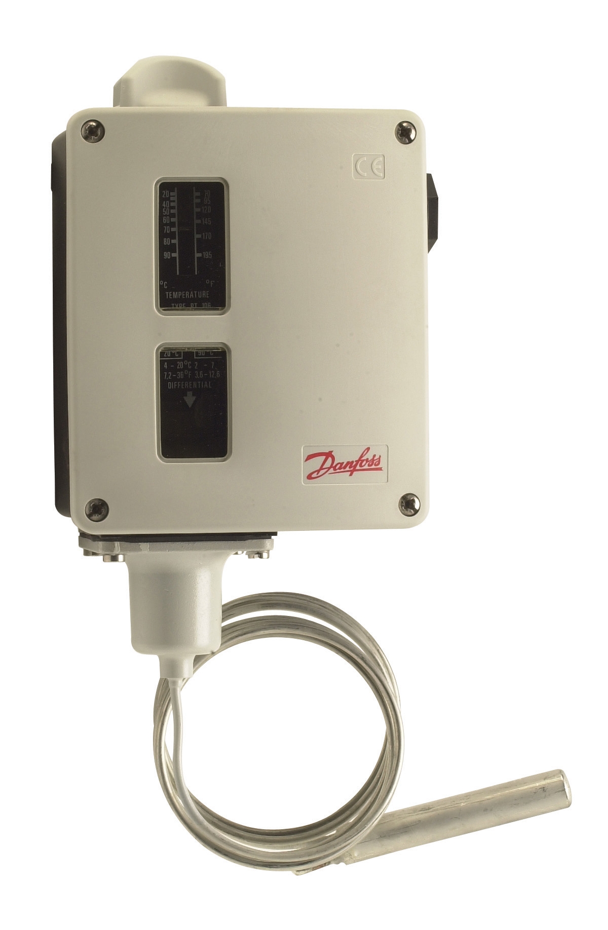
- Confirm adjustable differential setting matches application requirements. The Danfoss Thermostat RT 107 and RT 124 both offer 2-8°C adjustable differential. Wider differentials reduce cycling frequency but sacrifices setpoint accuracy.
- Visually inspect the flame detector tube for carbon accumulation or corrosion. UV detectors in oil burner applications accumulate soot; gas burners accumulate carbon monoxide residues. Clean with compressed air and soft cloth; never use solvents that attack optical coatings.
- Verify amplifier mounting in a location protected from water ingress. The Honeywell R7861A tolerates 0.5g continuous vibration, but Southeast Asian humidity and monsoon season moisture create condensation risk. Enclosure selection matters as much as component selection.
With the system de-energized:
- Measure thermostat contact resistance with a multimeter set to the 200-ohm range. Contacts should measure 0-2 ohms when closed, >10 megaohms when open. Corroded contacts read 10-50 ohms and must be cleaned or replaced.
- Verify the flame detector has proper high-voltage supply (typically 800-1200V for UV sensors). Use a high-voltage probe meter; do not assume supply voltage is correct without measurement.
- Confirm amplifier output relay coil resistance with an ohmmeter. Most industrial amplifier relays range 1-5 kΩ. Open or short circuits indicate amplifier failure.
With the burner system energized and under controlled conditions:
1. Set thermostat above current process temperature to initiate a call for heat.
2. Observe the control module's pre-purge timer. The fan should run without fuel for its programmed duration (typically 15-30 seconds for oil, 10-20 seconds for gas).
3. During the ignition phase, listen for the spark generator (audible clicking). Monitor the ignition window—typically 4-8 seconds. If spark occurs but flame doesn't establish, the solenoid may not be opening, or fuel supply pressure may be insufficient.
4. Upon flame establishment, the flame detector output should drive the amplifier relay coil, holding the solenoid energized. The UV detector responds to visible light from combustion—blue-orange flame in the 180-260 nm ultraviolet range.
5. Lower the thermostat setpoint. The control module should execute post-purge (fan running, fuel off) for its programmed duration, then stop.
A common failure mode in Southeast Asian installations: flame detectors fail to sense flame because the combustion chamber is too dark or fuel quality has degraded. Dark chambers reduce UV emission. Heavy fuel oil (HFO), common in Southeast Asia's marine industry, produces darker flame than light oil or gas. If flame detection fails but visual inspection confirms combustion, adjust the flame detector position or increase its sensitivity (if the amplifier offers adjustment).
Maintenance and Predictive Monitoring
For facilities with multiple burners or continuous operation, implement preventive maintenance intervals tied to component aging.
Thermostat Maintenance
- Every 12 months: Verify setpoint accuracy by comparing thermostat indication against an independent calibrated temperature instrument. Drift >2°C warrants calibration or replacement.
- Every 24 months: Remove the thermostat from the process and bench-test it in a controlled temperature bath. Plot the setpoint across its full range. Hysteresis >1°C indicates internal wear.
- Every 36 months: Replace thermostat if calibration drift exceeds acceptable limits. Bulb-type thermostats age; copper expansion characteristics degrade after 15-20 years.
- Monthly (oil burners): Clean the UV detector window with compressed air and a soft cloth. Oil burners produce soot that blocks ultraviolet transmission.
- Quarterly (gas burners): Inspect for carbon deposits. Gas combustion produces less soot but more carbon monoxide residues that accumulate on optical surfaces.
- Every 12 months: Test flame detector sensitivity using a test stand or the amplifier's built-in flame strength meter (if available). Response time should be <1 second from flame establishment to amplifier output.
- Every 24-36 months: Replace flame detector tube. Even with cleaning, optical transmission degrades. The Honeywell Cell C 7044 A 1006 is a field-replaceable consumable.
- Every 6 months: Verify amplifier relay coil function by manually de-energizing and re-energizing the control circuit. The relay should click distinctly; a silent relay indicates coil failure.
- Every 12 months: Test amplifier response time. De-energize the flame detector input; response time to output de-energization should be <100 milliseconds.
- Monitor vibration. The Honeywell R7861A withstands 0.5g continuous vibration, but burner mounting installations often exceed this, especially in industrial steam systems. If vibration exceeds specification, install vibration isolation mounts.
- Every 24 months: Inspect amplifier enclosure for corrosion, especially in salt-air environments (coastal Southeast Asian facilities). Replace enclosure gaskets if condensation is present.
Establish a quarterly inspection routine:
1. Record thermostat setpoint, differential, and current process temperature.
2. Photograph the flame detector window; compare to previous quarter. Increased soot indicates cleaning frequency must increase.
3. Measure amplifier supply voltage and relay coil current.
4. Test solenoid valve response time by commanding the burner on and off; measure time from control signal to audible click (valve opening).
5. Document any cycling behavior (burner turning on and off at intervals <10 minutes), which often indicates thermostat differential too narrow or setpoint instability.
Regional Considerations for Southeast Asian Facilities
Southeast Asia's tropical climate and industrial environment present specific challenges for Controls & Safety systems:
Humidity and Corrosion: Coastal facilities and monsoon-affected areas experience 80-95% relative humidity. Salt spray accelerates corrosion of thermostat bulbs and detector tubes. Specify stainless-steel components where available; schedule accelerated inspection intervals (quarterly instead of annually) in high-corrosion environments.
Fuel Quality Variation: Bunker fuel and heavy fuel oil common in Southeast Asian marine and power generation industries burn with lower flame temperatures and higher particulate content than refined fuels. This reduces flame detector signal strength. During commissioning, test flame detection sensitivity at the facility's actual operating conditions, not with test fuel.
Temperature Extremes: Equipment rooms without climate control experience 35-40°C ambient temperatures. The Honeywell Amplifier R 7861 A 1026 operates to 60°C, but sustained operation near maximum rated temperature accelerates component aging. Install cooling or ventilation if equipment room temperature exceeds 35°C.
Vibration from Adjacent Equipment: Industrial facilities often mount burner control systems near rotating machinery (fans, compressors, motors). Vibration coupling from adjacent equipment can degrade amplifier reliability. Isolate the control module and flame detector from vibration sources using elastomeric mounts.
With 35+ years of experience supporting industrial operations across Southeast Asia, 3G Electric understands these regional challenges. The components referenced—Danfoss thermostats, Honeywell detectors and amplifiers, and Pactrol control modules—are selected because they perform reliably in these conditions when properly commissioned and maintained.