Understanding Controls & Safety Relay Systems in HVAC Burner Applications
Controls & Safety systems in modern HVAC burner installations depend heavily on reliable safety relay circuits to manage interlocks between burner startup, flame detection, and emergency shutdown. A single failure in the safety relay or its associated interlock contacts can disable the entire control sequence, leading to unsafe operation or lockout conditions that halt production.
For HVAC contractors in Singapore managing industrial and commercial heating systems, understanding how safety relays integrate with pressure switches, flame detectors, and solenoid valves is essential. Over 35 years of experience serving Southeast Asian industrial facilities, 3G Electric has seen recurring patterns in safety relay failures that, when caught early, prevent costly emergency repairs and safety incidents.
This troubleshooting guide addresses the most common failure modes affecting safety relay circuits and interlock verification, providing step-by-step diagnostic procedures that contractors can apply to diagnose and resolve issues efficiently.
Identifying Safety Relay Contact Degradation and Electrical Continuity Issues
Safety relay contacts degrade gradually over thousands of operational cycles. In tropical climates like Singapore, moisture ingress, voltage spikes from solenoid coil de-energization, and arcing accelerate contact wear. When relay contacts begin to fail, the symptom pattern is predictable: intermittent lockouts, slow response to flame loss, or failure to energize solenoid valve coils.
Diagnostic Procedure for Contact Integrity:
- Visual Inspection: Remove the safety relay from its socket and inspect visible contacts for pitting, discoloration, or carbon buildup. Pitted contacts indicate arcing history and imminent failure.
- Continuity Testing: Using a digital multimeter set to resistance mode (Ω), measure continuity across normally-open (NO) contacts when the relay is energized. Resistance should be <0.1 Ω. Readings above 0.5 Ω indicate contact degradation and justify replacement.
- Dynamic Load Testing: Energize the relay coil and measure voltage drop across each contact under load (solenoid valve draw). Voltage drop >0.5 V at rated current indicates excessive contact resistance requiring immediate replacement.
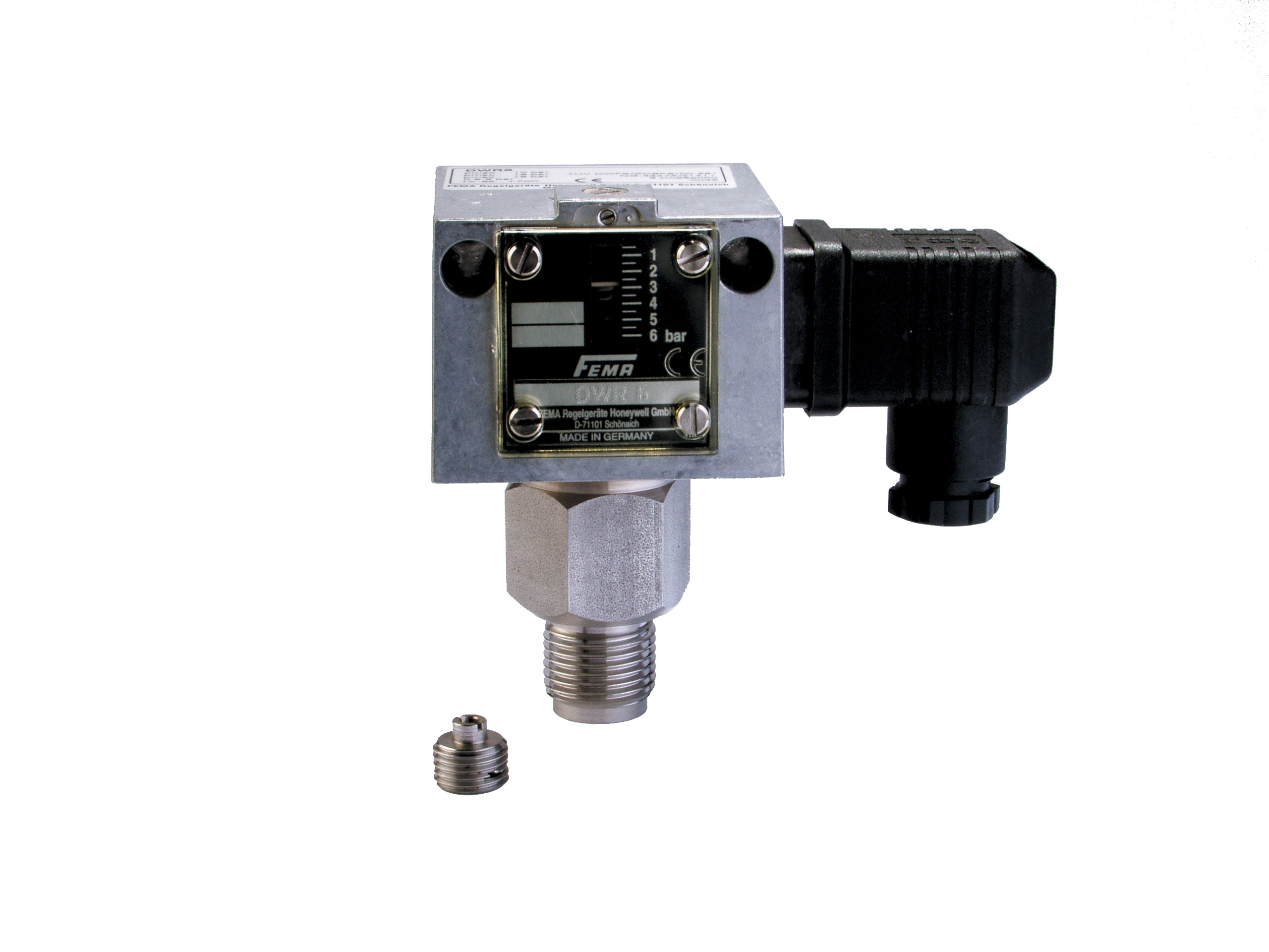
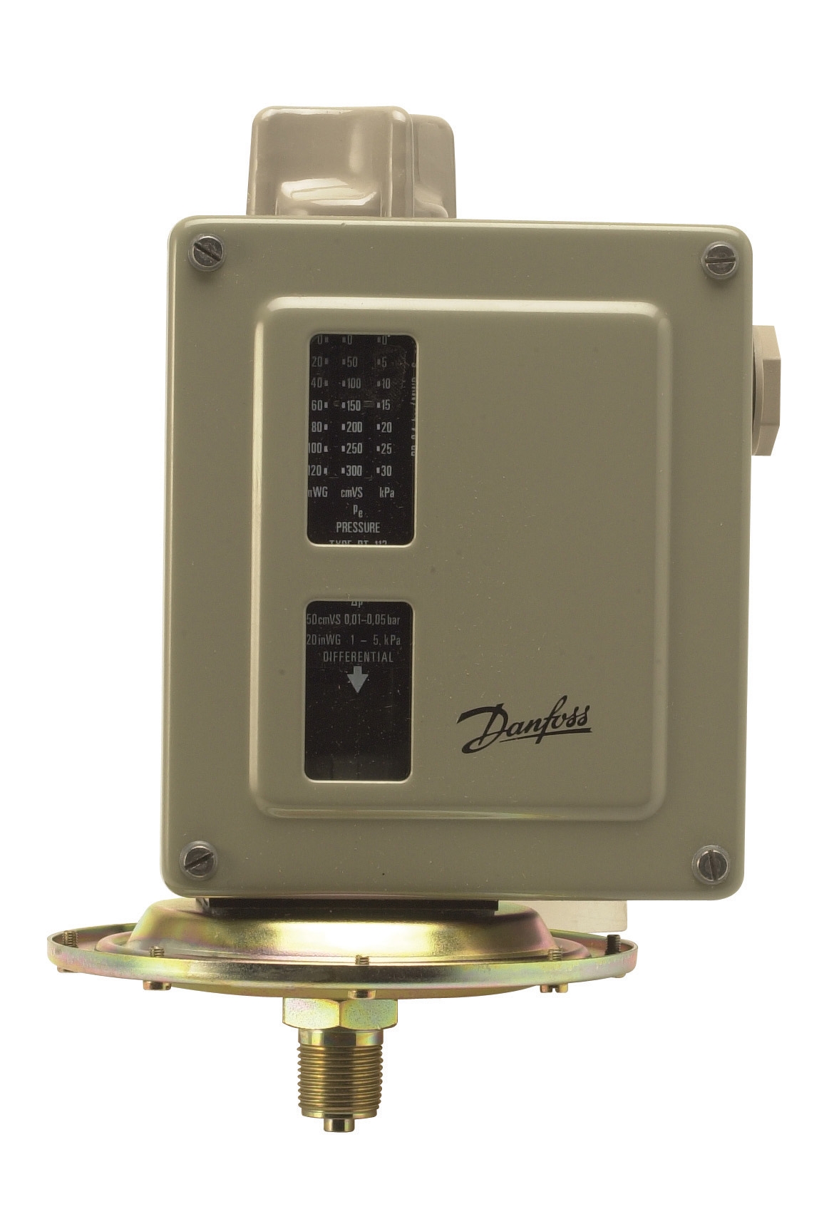
- Interlock Contact Verification: Test changeover contacts (as found on Danfoss Pressure switch RT 200 and Honeywell DWR16 Pressure switch) by confirming normally-closed (NC) contacts open when switching occurs. Failed interlock contacts prevent proper fuel shutoff during safety events.
Common degradation pattern: Contacts that measure acceptable on continuity testing but fail under dynamic load indicate microscoptic pitting that increases contact resistance under current flow.
Diagnostic Procedures for Safety Interlock Chain Failures
HVAC burner safety interlocks form a chain: air pressure switch → flame detector → safety relay → fuel solenoid valve. Any break in this chain creates a dangerous condition. The challenge for contractors is identifying which component broke the chain without bypassing safety logic.
Interlock Chain Testing Method:
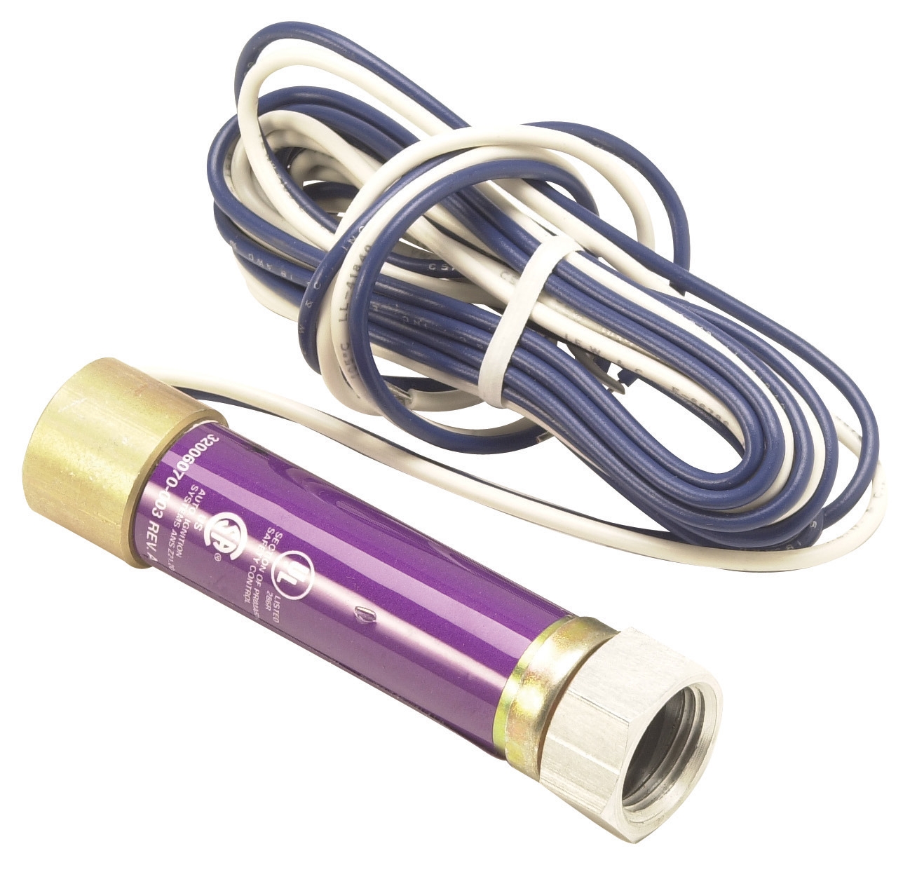
1. Establish Baseline Conditions: Document the sequence of events during normal startup. Safety relay should energize 2-3 seconds after air pressure switch closes. Flame detector (such as Honeywell Cell C 7027 A UV flame detector) should confirm flame within 5 seconds of ignition attempt.
2. Individual Component Isolation: Test each interlock independently by temporarily removing power from downstream components. For example, disconnect the flame detector signal and energize the safety relay manually. If the relay energizes, the problem lies in flame detection. If it does not, the problem is in the relay or upstream pressure interlock.
3. Time-Delay Verification: Safety relays incorporate fixed time delays (typically 10-12 seconds for ignition safety time). Use a stopwatch to measure actual delay from energize command to solenoid activation. Delays exceeding specification indicate relay age or internal timer component failure.
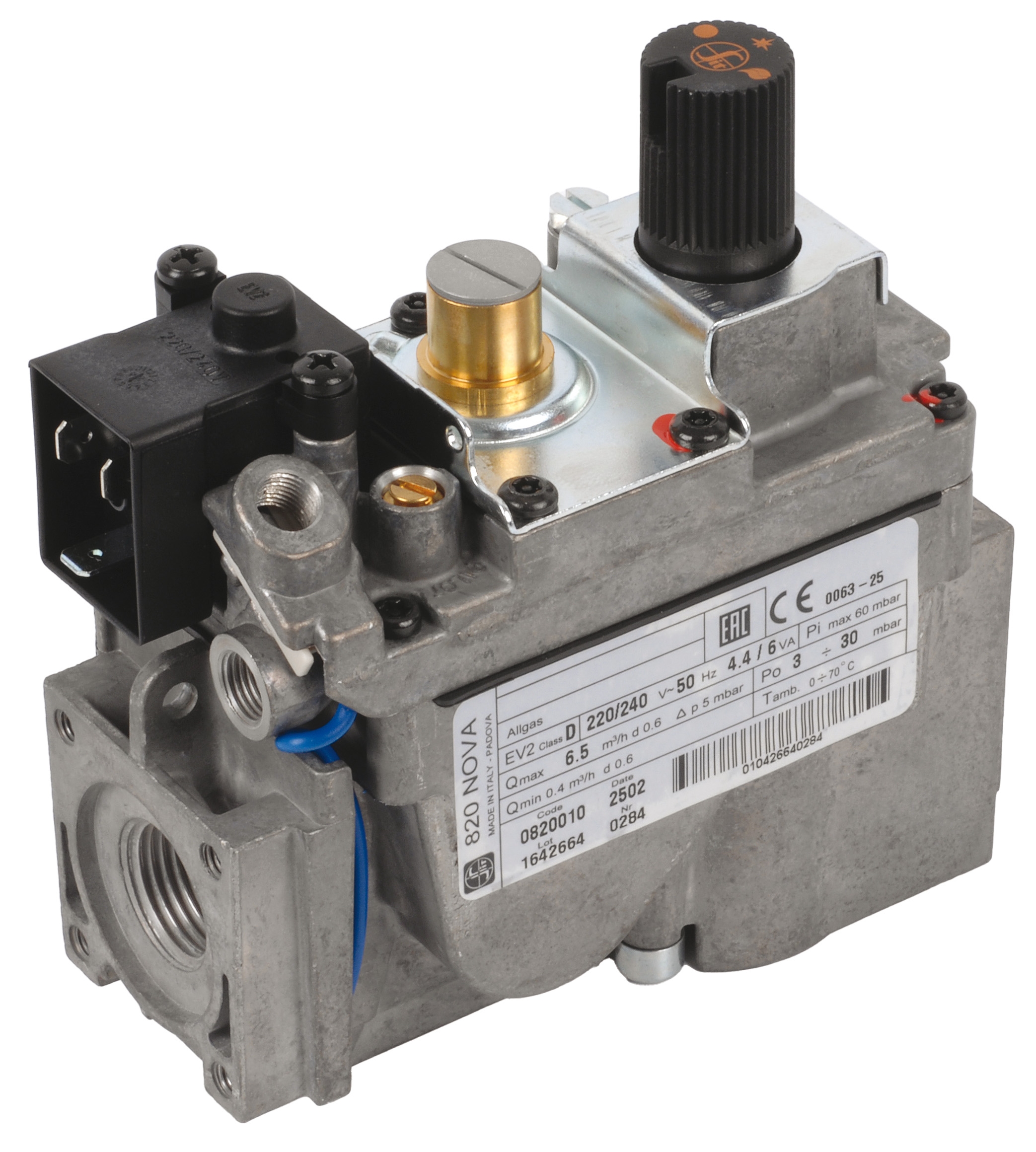
4. Solenoid Valve Response: When the safety relay does energize, the fuel solenoid valve should open within 200 milliseconds. A delayed response (audible click occurs >0.5 seconds after relay contacts close) suggests solenoid coil insulation failure, mechanical stiction, or pilot pressure loss. The Satronic Relay TF 974 includes a 10-second safety time for this verification window.
5. Lockout Circuit Verification: Simulate a flame loss condition mid-firing by unplugging the flame detector. The safety relay must de-energize within 2 seconds and latch into lockout mode, requiring manual reset. Failure to lockout is a critical safety defect requiring immediate component replacement.
Electrical Faults in Control Wiring and Coil Supply
Beyond the relay itself, faults in control wiring, power supply filtering, and coil insulation commonly cause intermittent relay operation that confuses diagnosticians.
Control Circuit Testing:
- AC Supply Voltage: Measure AC voltage at the relay coil terminals with the burner off. Singapore industrial supply typically operates at 230V ±10%. Voltage below 210V prevents relay pickup; voltage above 250V shortens coil life. The Pactrol Box P 16 B operates at 230V ±10% and is sensitive to supply deviations.
- Voltage Ripple Analysis: Use an oscilloscope to measure AC ripple on the control supply. Ripple >5% indicates failing transformer secondary or inadequate filtering. High ripple prevents clean relay pickup and causes chatter (rapid on-off cycling).
- Inductive Transient Suppression: When solenoid valve coils de-energize, they generate back-EMF spikes that can damage relay contacts and coil insulation. Confirm that a freewheeling diode or surge suppressor is installed across each solenoid coil. Missing suppressors cause relay coil insulation breakdown within weeks in high-cycle applications.
- Flame Detector Signal Integrity: UV flame detectors (Honeywell C 7027 A) produce 0-10 V DC signal proportional to flame intensity. Measure signal voltage at the safety relay input terminal. Voltage <2 V indicates weak flame or detector contamination. Voltage >10 V indicates preamp failure and requires detector replacement.
- Remove the safety relay from its socket. Using a multimeter, measure continuity between the relay base pins and the control circuit termination points. Intermittent open circuits (readings that fluctuate) indicate loose terminal screws, which are surprisingly common in facilities experiencing vibration.
- Trace all 24V DC control signal wiring and check for pinch-points near moving damper arms or rotating equipment. Chafed insulation creates ground faults that prevent reliable relay energization.
Troubleshooting Safety Relay Lockout Conditions
Lockout occurs when the safety relay de-energizes and prevents restart for 10-30 minutes without manual intervention. While lockout is a safety feature, repeated lockouts without apparent flame loss indicate either marginal flame detection, electrical noise on signal wiring, or relay contact bounce.
Lockout Root-Cause Diagnosis:
1. False Flame Loss: If lockout occurs immediately after ignition, the flame detector signal is insufficient. Check detector tube for soot accumulation (common in oil-fired burners). Clean with compressed air or replace the detector window. Verify detector mounting angle matches manufacturer specification—misalignment reduces flame view.
2. Signal Wiring Noise: Control signal wiring routed near motor starters or variable frequency drives (VFDs) picks up electrical noise that mimics flame loss. Relocate signal wiring away from power conductors, or install shielded twisted-pair cable with shield connected to control ground at one end only.
3. Relay Chatter: If you observe the safety relay clicking rapidly (multiple times per second), the relay is hunting between energize and de-energize states. This indicates marginal coil supply voltage or an oscillating flame signal. Measure coil supply voltage under load—if it drops below 210V during relay energization, upgrade the transformer secondary wire gauge or install a dedicated transformer for safety controls.
4. Manual Reset Failure: Some safety relays require a reset button press to clear lockout; others reset automatically when the fault clears. Verify which type is installed. If the relay remains locked after the flame loss condition is corrected, either the relay is welded internally or the reset circuit has an open contact.
Practical Maintenance and Replacement Strategy
For HVAC contractors managing facilities with multiple burners, a preventive replacement schedule for safety relays reduces unexpected lockouts. Industry best practice recommends replacing safety relays every 5-7 years in continuous-duty applications, even if they test functionally correct. Contact degradation is gradual and invisible until failure occurs under transient conditions.
When ordering replacement components, verify the exact relay model and coil voltage. The Satronic Relay TF 974 is a proven choice for burner capacity up to 30 kg/h and integrates cleanly with most legacy control systems. Pair relay replacement with a full safety interlock test following the procedures outlined above to confirm the entire chain functions correctly.
3G Electric's 35+ years of experience serving Singapore's industrial sector demonstrates that most control failures trace back to degraded relay contacts or electrical supply issues rather than complex sensor faults. By following systematic diagnostic procedures and maintaining proper preventive replacement schedules, HVAC contractors can eliminate unplanned shutdowns and keep heating systems operating safely.