Understanding Controls & Safety Through Sensor Redundancy Architecture
Controls & Safety in industrial burner systems hinges on the principle that single points of failure must not compromise operational integrity or personnel protection. Over 35 years distributing industrial equipment across Asia-Pacific, 3G Electric has witnessed how redundant sensing and cross-verification protocols transform burner reliability from acceptable to exceptional.
Sensor redundancy refers to the deployment of multiple independent detection devices that monitor the same physical condition—typically flame presence—through different physical principles. Cross-verification involves logic circuits that require confirmation from multiple sensors before executing critical actions, such as fuel shutoff or alarm activation.
This architecture addresses a fundamental challenge: a malfunctioning flame detector can trigger unnecessary shutdowns, disrupting production. Conversely, a failed detector that fails to detect genuine flame loss creates hazardous conditions. Redundancy with intelligent verification resolves this paradox.
Dual Flame Detection Systems: Ultraviolet and Ionization Cross-Confirmation
Industrial burner systems operating in Singapore's high-humidity, corrosive industrial environments benefit significantly from ultraviolet (UV) and ionization-based flame detection working in parallel.
The Honeywell Cell C 7044 A 1006 ultraviolet flame detector operates by monitoring the distinctive UV radiation signature emitted during hydrocarbon combustion. UV detection is exceptionally fast—responding within 200 milliseconds—and remains unaffected by ambient light or reflective surfaces common in industrial boiler rooms. However, UV sensors can develop surface contamination that temporarily reduces sensitivity.
Ionization detection, by contrast, monitors the electrical conductivity of the flame itself. As fuel burns, ions form in the flame zone, creating measurable current flow between electrodes. Ionization sensors are less sensitive to contamination but respond slightly slower (300-400 milliseconds) and require consistent electrode maintenance.
When both detection methods operate simultaneously:
- Flame confirmation logic requires both detectors to signal "flame present" before the burner remains energized. A single detector failure cannot cause loss of flame detection.
- Staged shutdown sequences activate when one detector fails, alerting operators while the system remains operational under the remaining detection method.
- Maintenance windows are identified automatically when sensor disagreement occurs, prompting technician review without forcing immediate shutdown.
This dual-input architecture prevents the two most dangerous scenarios: false shutdowns under normal operation and undetected flame loss due to sensor failure.
Amplifier-Level Cross-Verification and Signal Conditioning
Flame detection signals are weak—typically microvolts from UV sensors and nanoamperes from ionization cells. Industrial amplifiers must extract these signals from electrical noise while implementing verification logic that distinguishes genuine flame from interference.
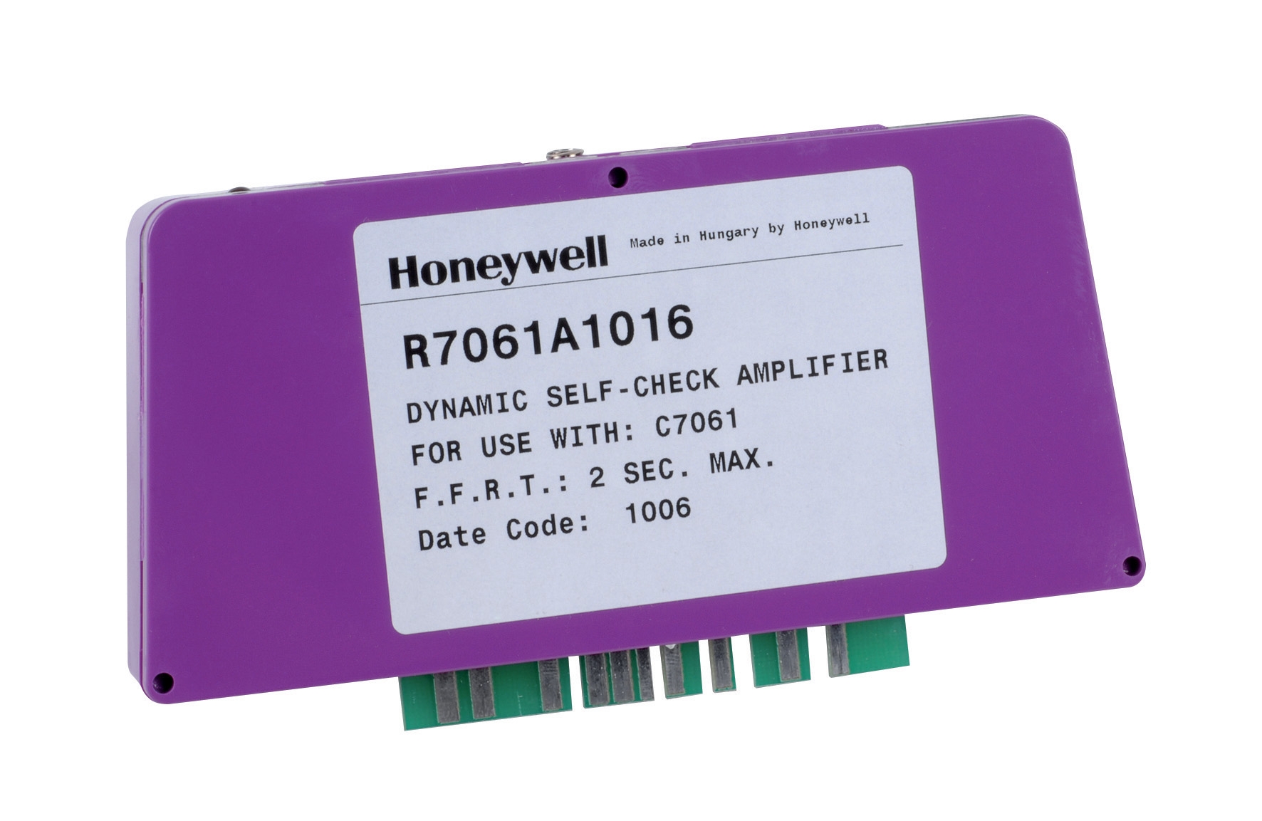
The Honeywell R 7861 A 1026 flame detector amplifier incorporates sophisticated signal conditioning suited to challenging Southeast Asian industrial environments. Operating across -40°C to 60°C while tolerating continuous 0.5 g vibration, this amplifier implements several cross-verification mechanisms:
Signal Confirmation Windows: The amplifier measures whether flame signals persist for minimum duration (typically 2-5 seconds) before confirming flame presence. Electrical transients or brief interference cannot trigger false flame recognition.
Frequency-Domain Filtering: UV sensors produce signals with characteristic frequencies (around 100-200 Hz) corresponding to combustion chamber frequency. The amplifier filters out-of-band noise while preserving authentic flame signatures.
Rate-of-Change Analysis: Genuine flame ignition produces rapid signal rise (milliseconds). The amplifier measures signal derivative to distinguish ignition transients from slow drift caused by contamination or sensor aging.
Temperature Compensation: The amplifier adjusts sensitivity based on internal temperature, accounting for how semiconductors and sensors behave across tropical Singapore's heat range. This prevents false high-temperature shutdowns during summer operation.
When dual amplifiers process signals from redundant detectors, cross-verification ensures both circuits must agree before safety-critical decisions execute. Disagreement between amplifiers triggers diagnostic alerts, guiding maintenance toward the source.
Thermostat-Detector Integration and Temperature-Flame Logic Gates
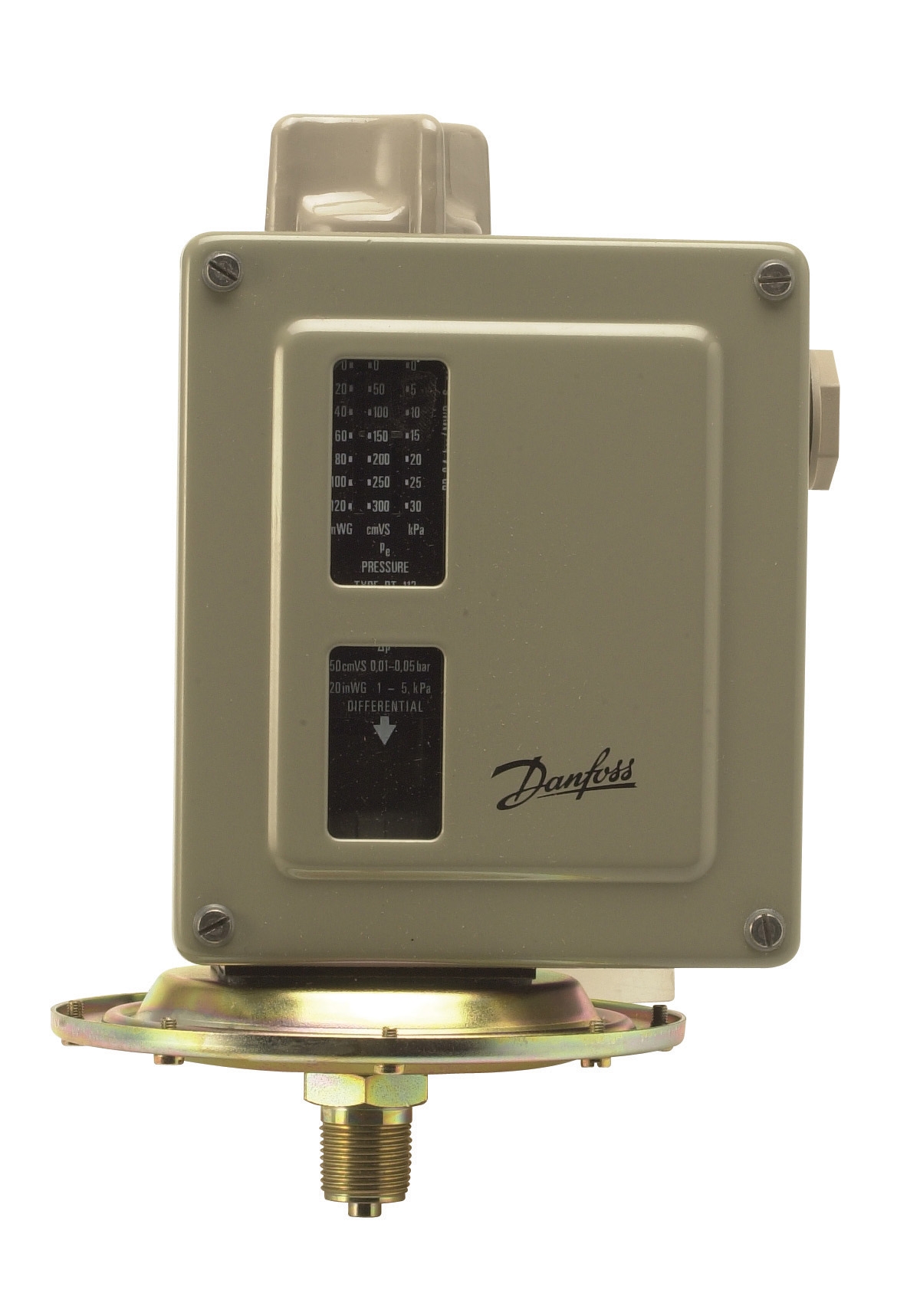
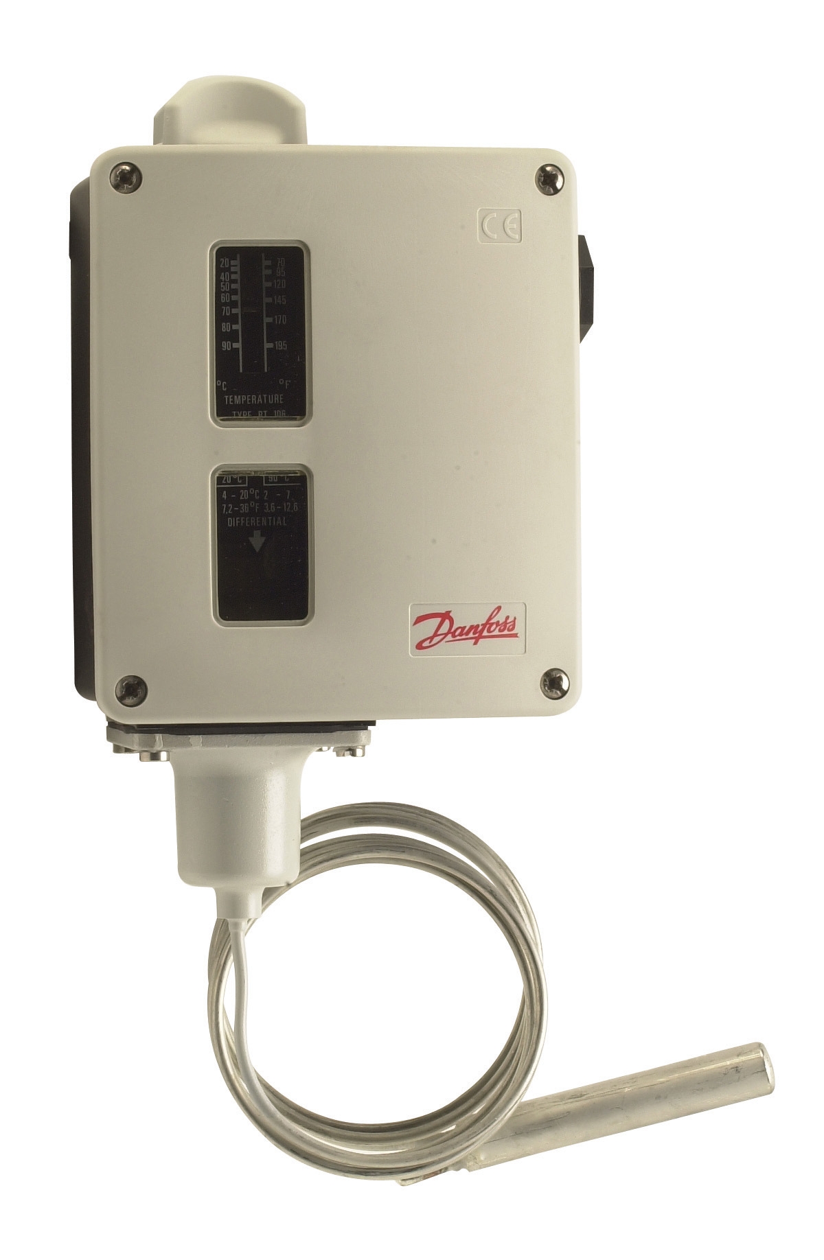
Temperature control and flame detection operate at different temporal scales but must coordinate seamlessly. Thermostats like the Danfoss RT 124 respond to slow temperature changes (integrating over minutes), while flame detectors respond to instantaneous combustion events (deciseconds).
Integrated control systems create a hierarchical verification structure:
Primary Logic Layer—Flame Detection: Flame detectors provide immediate yes/no signals regarding combustion activity. These signals execute the fastest safety responses (fuel shutoff via solenoids, ignition relay deactivation).
Secondary Logic Layer—Temperature Verification: Thermostat signals provide slower, broader confirmation that combustion events are actually heating the system as intended. A burner that ignites but transfers no heat to the medium (plugged burner, circulation pump failure, heat exchanger obstruction) is detected through temperature stagnation.
Integration Strategy: Control modules like the Pactrol CSS01 12 integrate both signals into decision logic:
- If flame detection signals flame presence AND thermostat signals rising temperature: Normal operation—continue fuel delivery.
- If flame detection signals flame presence BUT thermostat signals temperature decline: Alert technician to heat transfer failure; continue brief burner operation to allow manual intervention.
- If flame detection signals flame absence AND thermostat signals falling temperature: Execute emergency shutdown; no ignition retry without manual reset.
- If flame detection signals flame absence BUT thermostat signals rising temperature: Flag sensor failure for immediate inspection; maintain partial burner operation if operator override engaged.
This multi-criteria verification prevents shutdown cascades from single-sensor failures while protecting against genuine hazards.
Practical Implementation: Commissioning Sensor Redundancy Systems
Deploying redundant controls & safety systems requires systematic commissioning to ensure both sensors respond identically and logic circuits execute correctly.
Sensor Response Matching: During initial startup, operate the burner and record response times from both UV and ionization detectors. Acceptable variation is typically ±100 milliseconds. Greater divergence indicates sensor degradation, requiring recalibration or replacement before full operation.
Failure Simulation Testing: With the burner operating safely, temporarily block one detector's signal path (covering UV window, disconnecting ionization electrodes). The control system should immediately alert to sensor failure while maintaining operation through the remaining detector. Document alert messages and timing.
Amplifier Disagreement Protocol: Configure test conditions where one amplifier receives strong flame signal while the other receives weak signal. Verify that integrated logic generates "sensor verification failure" alarms rather than contradictory shutdown commands.
Temperature-Flame Coordination Verification: During burner startup, ensure:
- Ignition command → flame detection within 5 seconds → temperature rise begins within 20 seconds
- Any break in this sequence → diagnostic alert identifying which stage failed
- High humidity (95%+ RH) to verify UV sensor window clarity
- Temperature extremes (ambient 28-35°C) to confirm amplifier compensation
- Electromagnetic interference from nearby motors or welding equipment to validate filter effectiveness
These commissioning steps, while requiring 4-6 hours initially, prevent field failures and unplanned shutdowns that cost far more in lost production and emergency service calls.
Maintenance Protocols for Redundant Detection Systems
Redundant systems require proportional maintenance discipline. More detection points mean more components to inspect, yet redundancy also provides maintenance windows—you can service one detector while the other maintains safety coverage.
Monthly Visual Inspection: Check both UV sensor windows and ionization electrodes for soot accumulation. In combustion environments, both require cleaning every 2-4 weeks depending on fuel quality and air filtration.
Quarterly Functional Testing: Execute the failure simulation tests described above quarterly, documenting response times. Increasing divergence between detectors signals aging requiring replacement planning.
Annual Sensor Replacement Strategy: Most UV sensors and ionization cells reach end-of-life at 3-5 years in continuous-duty industrial applications. Plan staggered replacement—replace one detector annually—to maintain redundancy during replacement windows.
Amplifier Calibration: Honeywell R 7861 A amplifiers should be recalibrated annually in tropical climates. Temperature compensation circuits drift over time; without recalibration, sensitivity may degrade 10-15% annually.
Integration Testing After Maintenance: Any detector or amplifier replacement requires full cross-verification testing before returning to production operation. This prevents reintroduction of single-point failure conditions after maintenance work.
3G Electric's 35+ years supporting industrial equipment maintenance in Southeast Asia demonstrates that redundant control & safety systems pay dividends through reduced downtime, prevented hazardous situations, and simplified troubleshooting. When maintenance protocols match system complexity, operators gain confidence that their burner systems operate safely and reliably.