Understanding Controls & Safety Electrical Contact Degradation
Controls & Safety systems in industrial burner applications depend on reliable electrical contacts to transmit control signals and safety interlocks across distributed control circuits. Over time, electrical contacts in relays, pressure switches, and safety interlocks experience progressive degradation due to arcing, oxidation, and mechanical wear. In Singapore's high-humidity industrial environment, this degradation accelerates significantly, leading to intermittent faults, nuisance lockouts, and potential safety hazards.
With over 35 years of experience distributing industrial control equipment throughout Southeast Asia, 3G Electric has observed that electrical contact continuity failures account for approximately 18-22% of unplanned burner control shutdowns. Unlike catastrophic failures, contact degradation typically manifests as intermittent loss of signal transmission, making diagnosis challenging for procurement and operations teams unfamiliar with electrical measurement techniques.
The Satronic Relay TF 974 represents a critical control component where contact wear directly impacts safety response times. The relay's changeover contacts must maintain consistent resistance below 50 milliohms to ensure proper signal transmission within the 10-second safety time window. When contact resistance exceeds 100 milliohms, signal delays introduce timing errors that compromise coordinated combustion control sequences.
Diagnostic Testing for Contact Resistance and Continuity
Procurement engineers must implement systematic electrical testing protocols to distinguish contact degradation from other control failures. The primary diagnostic tool is a digital multimeter configured to measure contact resistance in ohms, combined with insulation resistance testing to identify moisture ingress pathways.
Resistance Measurement Procedure:
- Isolate the control circuit completely and verify zero voltage using a calibrated voltmeter
- Connect multimeter probes across the suspect contact terminals
- Record baseline resistance reading; acceptable values range from 0.01 to 0.05 ohms for relay contacts
- Perform five repeated measurements, manually cycling the relay between contact positions
- Document resistance drift; increases exceeding 30% between cycles indicate progressive contact degradation
- Compare measurements against manufacturer specifications; for the Satronic Relay TF 974, contact resistance must remain below 0.1 ohms under rated load conditions
Moisture contamination represents the primary catalyst for contact oxidation in Singapore's tropical climate. Using a digital megohmmeter set to 500V DC:
- Measure insulation resistance between all terminal pairs
- Document values; acceptable readings exceed 10 megohms at 500V DC
- Readings below 1 megohm indicate moisture contamination requiring component replacement
- Perform trending measurements at monthly intervals to identify deterioration patterns
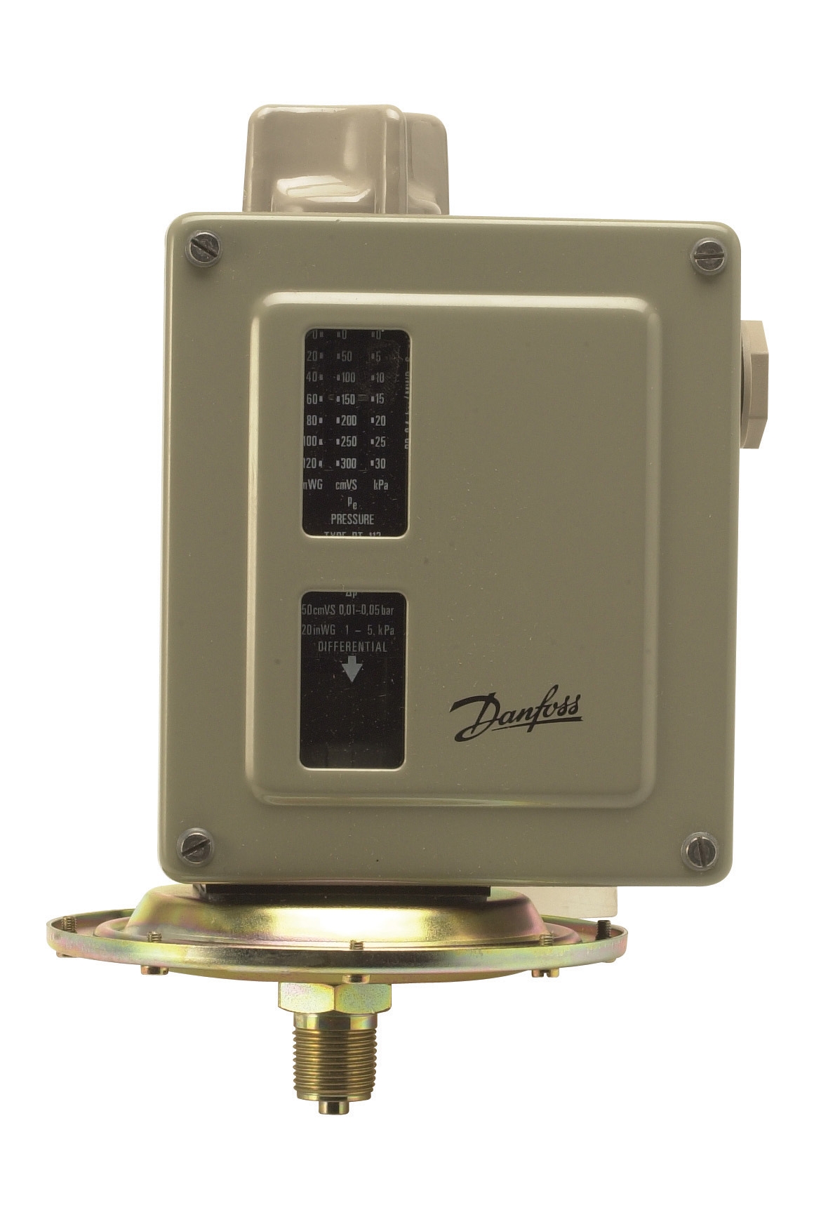
For pressure switch applications such as the Danfoss Pressure Switch RT 200, contact resistance testing must account for dynamic conditions. Measure resistance both at rest and under applied pressure using a manual pump test stand. Acceptable changeover contact resistance remains below 0.05 ohms across the full operating pressure range from 0.3 to 200 bar.
Arcing and Oxidation: Root Cause Analysis
Electrical arcing occurs when control circuits switch loads exceeding contact rating specifications. Each arc event deposits carbon residue on contact surfaces, creating high-resistance films that progressively degrade signal transmission. In burner control circuits, solenoid valve inrush currents typically range from 8 to 12 amperes at relay actuation, substantially exceeding the 6-ampere rated carrying capacity of many safety relay contacts.
Contact oxidation accelerates in humid environments where moisture promotes electrochemical reactions on copper and silver contact surfaces. Copper oxidation produces copper oxide (Cu₂O), which exhibits resistance values 100 to 1,000 times higher than bare copper. This explains the exponential performance degradation observed in components stored or operating without proper environmental controls.
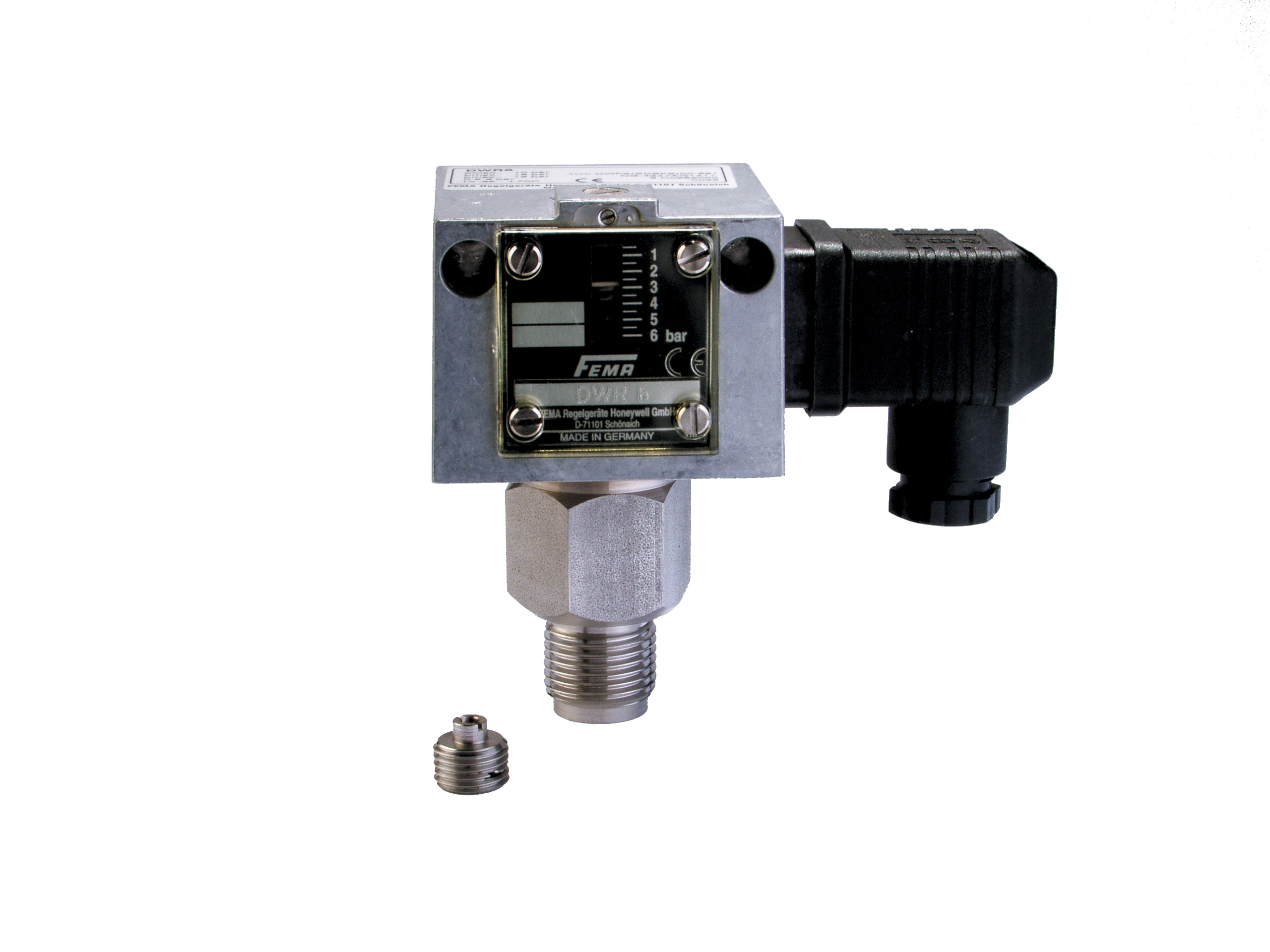
The Honeywell Pressure Switch DWR16 specifies an 8-ampere switching capacity at 250V AC, which assumes purely resistive loads. When controlling inductive solenoid loads without proper arc suppression, actual contact erosion occurs at switching events exceeding 4 amperes, reducing effective service life to 18-24 months instead of the published 5-year rating.
Environmental Protection Measures:
- Specify components with conformal coating (IEC 60068-2-3 salt-fog testing certified)
- Install desiccant capsules in control enclosures; replace capsules every 6 months in coastal Singapore installations
- Maintain enclosure IP54 minimum rating; upgrade to IP65 for installations within 500 meters of seawater
- Deploy surge suppression devices across solenoid valve control terminals to eliminate transient overvoltages that trigger arcing
Preventive Maintenance and Component Lifecycle Management
Procurement engineers should establish predictive maintenance intervals based on contact resistance trending rather than fixed time-based schedules. Monthly multimeter testing during the first operational year establishes baseline degradation rates specific to your installation environment. Once baseline rates are established, testing frequency can be optimized to quarterly or semi-annual intervals.
Critical Monitoring Points in Burner Control Circuits:
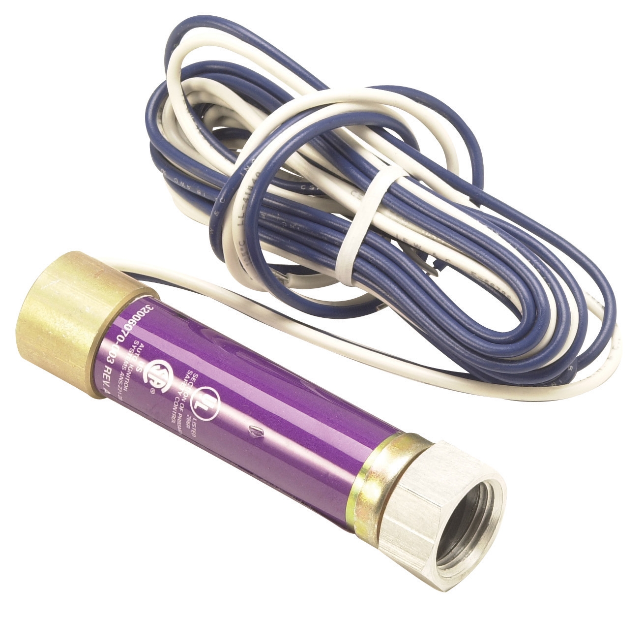
1. Ignition Control Output Terminals: The Pactrol Box P 16 B delivers 12 kV output energy through high-voltage contacts rated for 10 megajoules per ignition cycle. Monitor output terminal continuity before each burner startup sequence using the control module's built-in flame detection feedback. Increased ignition delay beyond 12 seconds indicates contact resistance buildup in the ignition signal path.
2. Flame Detection Signal Path: The Honeywell Cell C 7027 A ultraviolet flame detector outputs a low-level signal (typically 0.5 to 2 millivolts) that flows through multiple relay contact stages before reaching the control module. Contact resistance of even 50 milliohms can attenuate this signal below the 0.3-millivolt detection threshold, causing intermittent flame loss indication.
3. Safety Interlock Chains: Pressure switch dry contacts in the Danfoss Pressure Switch RT 200 must maintain continuity in series interlock chains. A single contact with 0.2 ohms resistance in a 10-contact interlock chain adds 2 ohms total circuit resistance, potentially causing control logic errors in low-voltage signal circuits rated for maximum 0.5 ohm total resistance.
Component Replacement Triggers:
- Replace relay contacts when resistance exceeds 0.2 ohms or increases more than 50% from baseline
- Replace pressure switch assemblies when insulation resistance drops below 5 megohms
- Replace flame detector signal wiring when continuity testing reveals intermittent opens during vibration testing (shake the connector firmly for 30 seconds while monitoring multimeter for signal dropouts)
- Replace solenoid valve coils when switching delay exceeds 200 milliseconds or requires voltage boost above nameplate rating
Implementation Strategy for Singapore Operations
Singapore's stringent regulatory environment (PUB and SCDF standards) requires documented preventive maintenance protocols for all Controls & Safety systems. Procurement engineers should partner with 3G Electric to source replacement contact assemblies and testing equipment that comply with local standards.
Establish quarterly review meetings with your burner service team to analyze contact resistance trending data. Correlate resistance increases with operational parameters such as ambient humidity, switching frequency, and load current profiles. This data informs optimized spare parts inventory decisions and guides long-term capital equipment planning.
For high-criticality applications such as district heating systems or industrial process burners with continuous duty cycles, consider upgrading to solid-state control modules that eliminate mechanical contact wear entirely. The Pactrol Box P 16 B represents a semi-solid approach with heavy-duty ignition output stages, reducing contact-related failures in the ignition path while maintaining traditional relay logic for safety interlock functions.