Understanding Controls & Safety Relay Architecture in HVAC Systems
Safety relays form the backbone of modern HVAC burner control systems, providing the essential logic between flame detection sensors, ignition modules, and shutdown mechanisms. In Singapore's hot and humid industrial environment, these relay circuits face constant stress from thermal cycling, electrical transients, and corrosive salt-laden air. With 35+ years of experience distributing industrial control equipment, 3G Electric has observed that safety relay failures account for approximately 18-22% of unscheduled burner shutdowns in Southeast Asian facilities.
Unlike simple on/off relays, safety-rated control relays implement redundant switching paths, time-delay functions, and monitoring circuits designed to fail safe—meaning any component fault triggers a shutdown rather than a dangerous operating state. The Satronic Relay TF 974 exemplifies this architecture, combining 10-second safety time windows with dual-channel monitoring to prevent nuisance lockouts while maintaining protective function.
The critical distinction contractors must understand is the difference between response delay (the time required for a relay to energize or de-energize after receiving a control signal) and safety time (the deliberately programmed delay designed to allow burner stabilization before the relay permits continued operation). Confusing these two concepts leads to unnecessary component replacement and extended troubleshooting cycles.
Diagnostic Procedures for Safety Relay Response Delays
Step 1: Establish Baseline Response Timing
Begin every relay troubleshooting session by measuring actual response times against manufacturer specifications. Using a digital multimeter with continuity testing capability or a dedicated relay test instrument:
- Measure the time interval between applying 24V control signal to the relay coil and observing continuity across the safety contact terminals
- Compare measured times against the relay datasheet specifications (typically 50-200 milliseconds for standard control relays)
- Document three consecutive test cycles to identify intermittent timing variations that indicate worn contacts
Response delays exceeding specifications by more than 30% suggest spring fatigue, contaminated contacts, or coil winding degradation. In Singapore's tropical climate, salt corrosion accelerates contact deterioration; a relay operating normally six months ago may now exhibit 150-300ms delays due to atmospheric ingress.
Step 2: Verify Coil Continuity and Resistance Measurements
Safety relay coils typically exhibit DC resistance values between 400-600 ohms for 230V units operating at 50 Hz. Using an ohmmeter:
- Disconnect all power sources before measuring
- Test resistance between coil terminals; values outside ±5% of rated specification indicate winding insulation breakdown
- Measure resistance between coil terminals and the relay chassis; any reading below 10 megohms suggests moisture ingress—common in coastal Singapore facilities
- Compare resistance measurements to baseline values recorded at installation; sudden increases of 15-20% indicate imminent failure
Winding resistance increases are irreversible—replacement is necessary rather than troubleshooting. The Satronic Relay TF 974 includes sealed contact chambers to resist moisture ingress, making it superior to unsealed designs in maritime industrial environments.
Step 3: Contact Arcing and Switching Noise Analysis
Safety relays fail prematurely when switching circuits containing inductive loads (solenoid valves, ignition transformers) without proper arc suppression. Indicators of contact arcing include:
- Audible crackling or popping sounds during relay energization/de-energization
- Radio frequency interference affecting nearby electronic controls
- Visible pitting or molten residue on contact surfaces upon visual inspection
- Erratic flame detection response immediately following relay activation
Arcing damage is progressive—a slightly pitted contact pair may function for weeks before degrading into complete failure. Contractors should install transient suppression diodes across inductive loads if not already present. For the ignition module circuit, the Pactrol Box P 16 B includes integrated arc suppression, eliminating this failure mode.
Troubleshooting Control Circuit Faults and Signal Path Verification
Flame Detection Signal Path Testing
The control circuit begins at the flame detector and flows through the safety relay to the main burner control. Common failure points in this signal path:
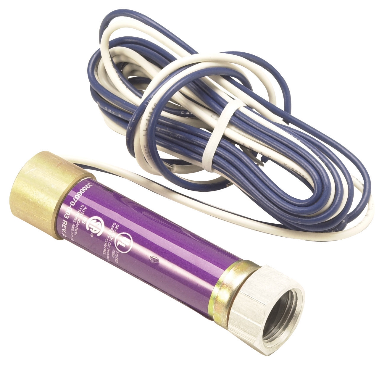
UV Flame Detector Issues: The Honeywell Cell C 7027 A 1049 detects ultraviolet radiation from the flame. Verify proper signal output by:
- Measuring DC voltage at the detector output terminal (typically 0-10V depending on flame intensity)
- Confirming voltage increases to 8-10V within 2 seconds of burner ignition
- Testing detector response with a burner test flame if field commissioning is available
- Checking mounting position—detectors require clear line-of-sight to flame; any obstruction from scale buildup or insulation debris prevents signal generation
Detector failure often manifests as zero voltage output regardless of flame presence. Causes include failed internal amplifier circuits, moisture condensation on optical components, or cracked protective windows from thermal shock during rapid burner cycling.
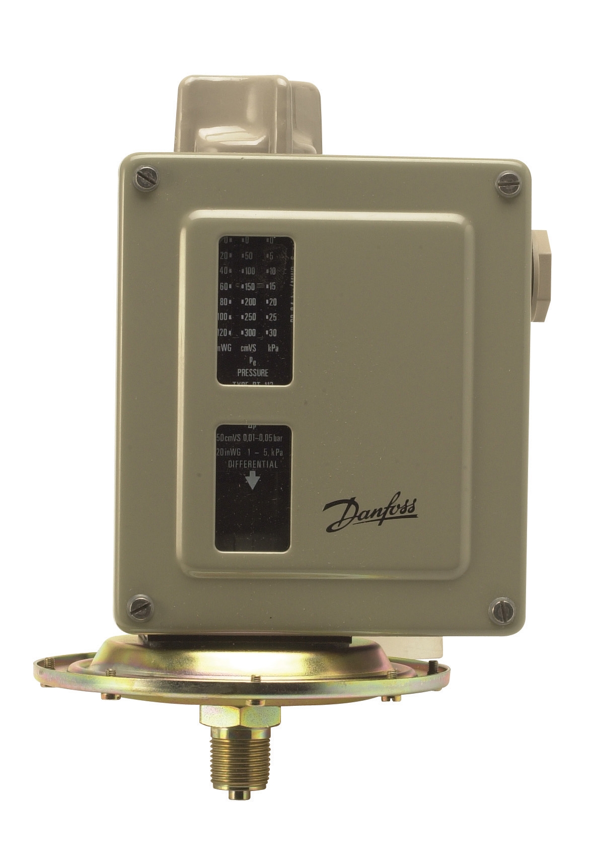
Pressure Signal Monitoring: Pressure switches like the Danfoss Pressure Switch RT 200 convert physical pressure changes into electrical contacts that feed the safety relay. Testing procedure:
- Apply controlled pressure to the switch inlet using a manual pump or compressed air supply
- Observe contact closure at the setpoint pressure (typically 0.3-0.5 bar for burner air proving)
- Verify contact opening occurs when pressure drops 10-15% below setpoint (differential characteristic)
- Measure contact resistance at closed position—should be <0.5 ohms; higher values indicate contact degradation
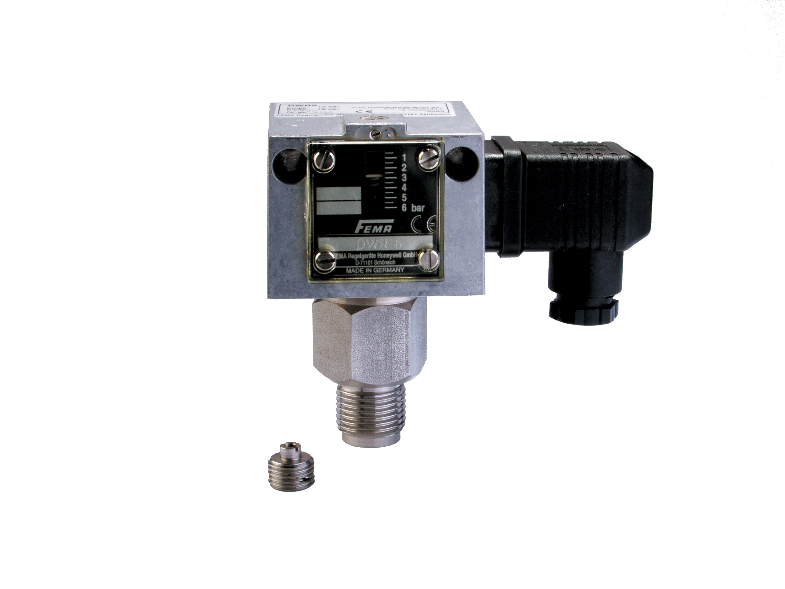
The Honeywell DWR16 3/16 bar pressure switch provides identical functionality with additional mechanical robustness for vibration-prone installations. In Singapore's humid coastal regions, pressure switches with stainless steel housings resist corrosion better than standard mild steel designs.
Safety Relay Input Verification
Once flame and pressure signals are confirmed functional, verify they reach the safety relay terminals:
- Disconnect the signal cable at the relay input terminal
- Measure voltage/resistance at the cable end using a multimeter
- Compare measurements to those obtained directly at the source (detector output, pressure switch contact)
- Voltage drops >1.0V over the signal cable indicate excessive resistance—clean connectors, repair corroded terminals, or replace degraded cable
Signal degradation is particularly problematic in HVAC installations where control wiring shares conduit with high-voltage power lines. Induced electrical noise can false-trigger safety relays or prevent legitimate signals from reaching the relay. Always route control signal cables in separate conduit, minimum 6 inches separation from power lines.
Safety Relay Lockout Cycles and Reset Verification
Understanding Non-Latching Lockout Behavior
When flame loss is detected mid-burner-operation, safety relays enter a locked-out state requiring manual reset. The duration of this lockout varies by design:
- Automatic reset relays (common in older systems) allow burner restart immediately upon flame restoration; these are less preferred because they cannot distinguish between momentary flame dropout and genuine safety events
- Manual reset relays require operator intervention to clear the lockout condition; this ensures maintenance personnel verify the cause before restart
- Timed automatic reset relays (preferred) wait 30-120 seconds before permitting restart, allowing flame to stabilize and system transients to settle
The Satronic Relay TF 974 implements a 10-second safety time before permitting pilot flame ignition, followed by approximately 12-second ignition delay before demanding main flame establishment. If the relay triggers lockout immediately after reaching this sequence, verify:
1. Flame detector is receiving actual flame light: Place a burner test card in the flame path; the detector should suppress any false signals and maintain stable output
2. Safety relay reset circuit is functional: Apply manual reset signal per relay documentation; the relay should de-energize then re-energize after a short delay
3. Control circuit is not in a fault state: Check for any pilot light pressure loss, ignition transformer issues, or solenoid valve sticking that could prevent stable flame establishment
Preventing Nuisance Lockouts Through Proper Tuning
Nuisance lockouts—safety shutdowns occurring during normal operation without legitimate safety hazards—represent the leading cause of HVAC contractor callbacks in Singapore. Primary causes include:
Inadequate Flame Signal Strength: The Honeywell C 7027 A 1049 flame detector's sensitivity is factory-set for typical burner installations. However, excessive scale buildup on furnace windows, contaminated detector lenses, or incorrect detector mounting position reduces signal strength. Solution: Clean detector optical surfaces with isopropyl alcohol on a lint-free cloth; verify line-of-sight angle is within ±15 degrees from flame axis; confirm mounting distance matches burner manufacturer specifications (typically 2-4 inches from flame envelope).
Pressure Switch Oscillation: Pressure switches set at the threshold of air-proving pressure may chatter if system pressures fluctuate slightly. The Danfoss Pressure Switch RT 200 includes adjustable dead-band characteristics. Proper tuning requires setting the switch 10-15% above minimum required pressure, preventing chatter while maintaining safety margin. If nuisance trips occur shortly after burner startup, increase setpoint pressure by 0.05 bar and retest.
Electrical Noise Triggering False Signals: In facilities with variable frequency drives, induction welders, or large motor starters nearby, electromagnetic interference can induce voltage transients in control signal lines. Mitigation:
- Install ferrite suppressors around signal cables entering the relay
- Upgrade signal cables to shielded twisted-pair type with shield grounding at control panel
- Increase relay input thresholds if the relay provides adjustable sensitivity (consult specific relay documentation)
Practical Commissioning and Preventive Maintenance Protocol
After completing repairs or relay replacement, follow this commissioning sequence:
1. Safety function verification: Interrupt flame signal manually (cover detector); burner should shut down within 2 seconds
2. Restart sequence confirmation: Clear lockout; burner should attempt ignition, establish pilot flame within 30 seconds, then establish main flame within 60 seconds
3. Sustained operation: Run burner for minimum 5 minutes at full capacity; no lockouts should occur
4. Pressure and temperature stability: Verify system achieves target setpoint temperature without overshoot or cycling
Establish preventive maintenance intervals:
- Every 6 months: Visual inspection of relay contacts for pitting; measurement of response times; verification of flame detector optical cleanliness
- Every 24 months: Full replacement of pressure switch if operation is in coastal/corrosive environment; inspection and potential reseating of relay contacts
- Every 36 months: Complete relay replacement regardless of apparent functionality—this prevents catastrophic failure at critical times
With 35+ years of distributor experience, 3G Electric recommends maintaining spare relays and pressure switches on-site for rapid replacement rather than extended troubleshooting downtime. The cost of carrying spare components is minimal compared to lost HVAC availability in Singapore's tropical climate.