Understanding Controls & Safety Integration in Modern Industrial Systems
Controls & Safety represents the critical intersection of temperature management and combustion monitoring in industrial heating applications. For Singapore industrial professionals operating in humid tropical climates with stringent regulatory requirements, effective integration of these systems is non-negotiable. Drawing on over 35 years of experience distributing industrial equipment across the region, 3G Electric has observed that most operational failures stem not from component defects, but from poor integration between temperature control and flame detection circuits.
The fundamental principle underlying integrated Controls & Safety architecture is redundancy with intelligence. Your system must simultaneously monitor multiple parameters—flame presence, burner temperature, inlet pressure, and safety interlocks—while maintaining deterministic response times measured in milliseconds. This is not optional; it is mandated by international safety standards including EN 298 and Singapore's Fire Safety Code.
When temperature control devices operate in isolation from flame detection systems, you create dangerous blind spots. A thermostat may signal "call for heat," but if flame detection is delayed or unreliable, fuel accumulates in the combustion chamber before ignition occurs. This scenario has caused countless industrial incidents across Southeast Asia. Conversely, flame detection without responsive temperature control leads to hunting—repeated ignition cycles that degrade burner components and waste energy.
Selecting Complementary Temperature and Flame Detection Components
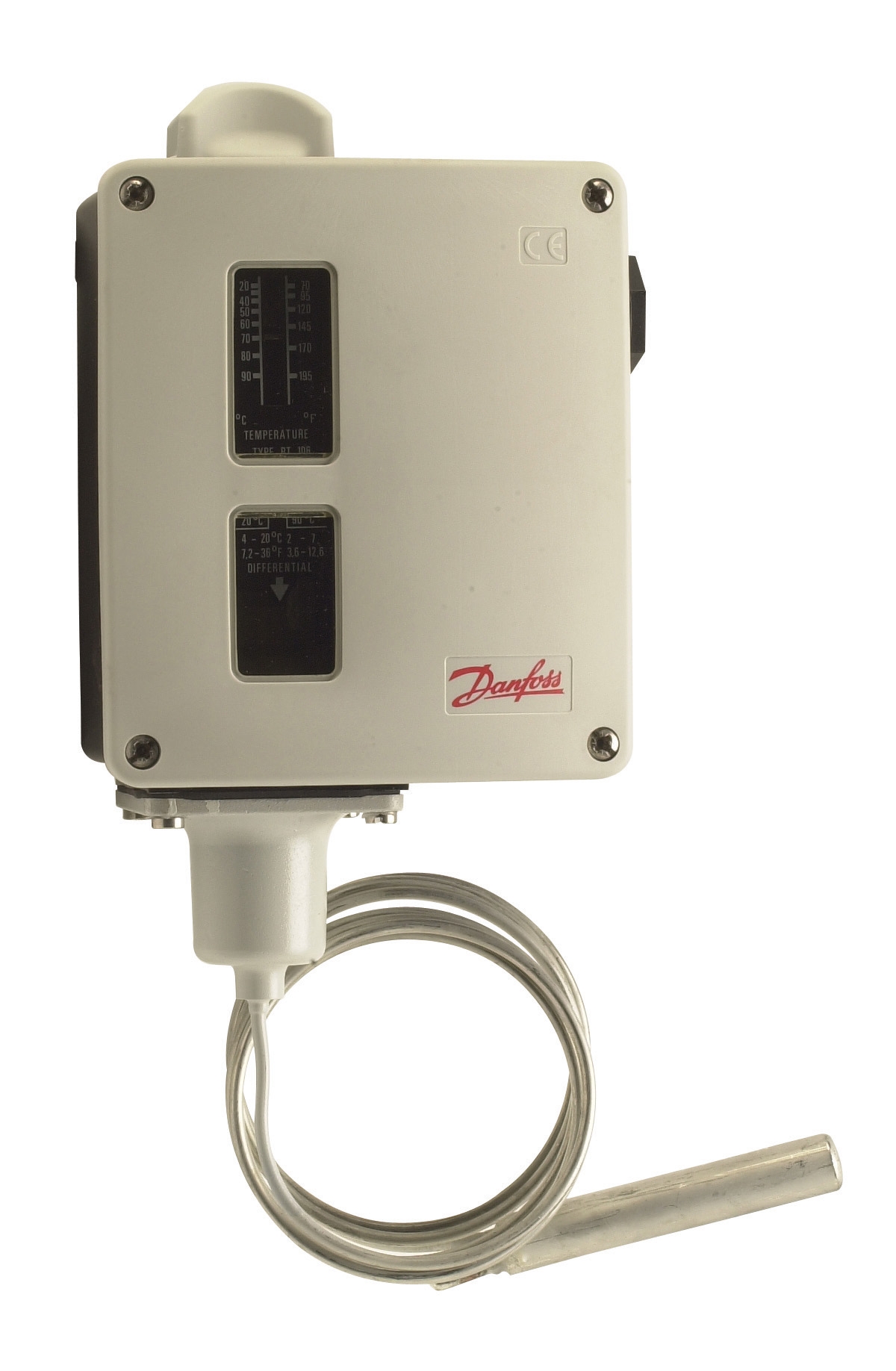
Temperature regulation in modern Controls & Safety systems begins with precision thermostats that provide clear, unambiguous signals to downstream control logic. The Danfoss RT 124 exemplifies this requirement. As a bulb-actuated thermostat with adjustable differential and neutral zone capability, it delivers stable switching behavior across the operating range typical in Singapore's industrial facilities (18°C to 40°C ambient, with process temperatures reaching 100°C or higher).
The RT 124's single-pole changeover contact design is critical: it provides positive switching certainty without the hesitation or drift that analogue sensors can introduce. The adjustable differential—typically 2°C to 5°C depending on application—prevents the "chatter" that occurs when setpoint and actual temperature oscillate around a fixed threshold. This stability is essential because unreliable thermostat signals directly degrade flame detector response timing.
Complementing temperature control, flame detection must provide equally deterministic signals. The Honeywell Cell C 7044 A 1006 ultraviolet flame detector serves this function through proven UV sensing technology. UV detection offers particular advantages in Singapore's industrial context: it is immune to ambient light fluctuations (critical near windows in equatorial facilities), responds in approximately 300 milliseconds to real flames, and avoids false positives from hot surfaces or reflected radiation.
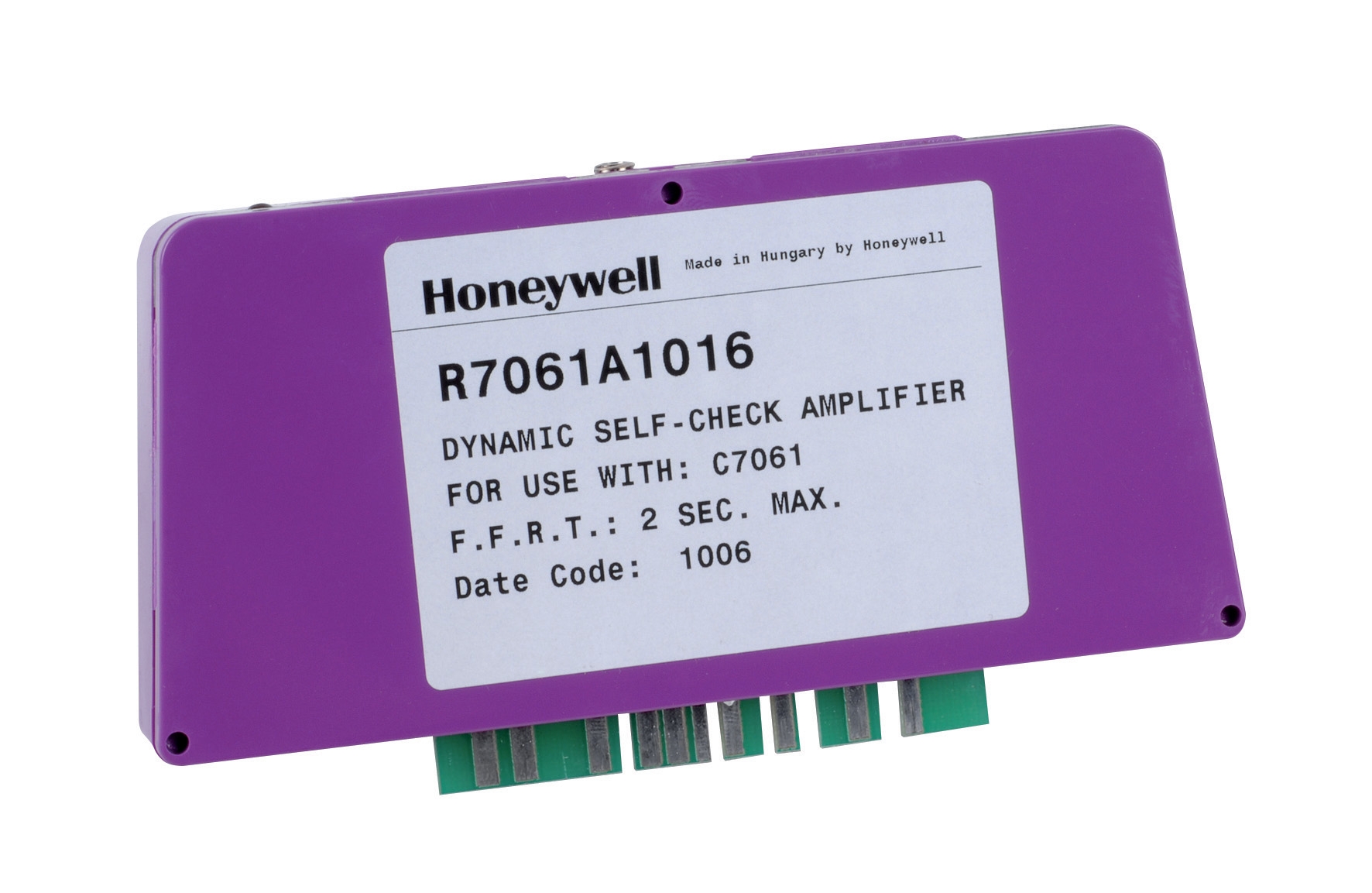
However, the flame detector itself provides only raw sensory input. The Honeywell Amplifier R 7861 A 1026 processes this signal and integrates it into your Controls & Safety logic. This amplifier operates across -40°C to 60°C (covering Singapore's non-refrigerated and minimally conditioned plant rooms) and tolerates 0.5 g continuous vibration—the baseline for industrial machinery. The R7861A 1026 implements the critical "fail-safe" architecture: if signal is lost or invalid, the amplifier defaults to burner shutdown, not continued operation.
Integration of these three components—thermostat, flame detector, and amplifier—requires understanding their electrical characteristics and response times:
- Thermostat response time: 30-60 seconds (thermal mass of bulb sensor)
- Flame detector response time: 0.3-0.5 seconds (UV sensor electronics)
- Amplifier response time: 0.1-0.2 seconds (relay switching)
- Overall system response to flame loss: 3-5 seconds (safety standard requirement)
Your wiring and sequencing logic must account for these timing differences. The thermostat change-of-state must arrive at the control module with sufficient lead time to prepare the amplifier for incoming flame detection signals. This is not intuitive and requires careful commissioning.
Control Module Selection and Burner System Architecture
The Pactrol CSS01 12 housing control module represents the integrated solution that consolidates thermostat input, flame detection processing, and burner ignition sequencing into a single, certified assembly. For Singapore facilities operating small to medium forced-air burners (up to 60 kW), this module eliminates the field integration complexity that often causes failures.
The CSS01 housing integrates three critical functions:
1. Timed relay circuit: Enforces the pre-purge cycle (typically 15-30 seconds) that clears unburned fuel from the combustion chamber before ignition is attempted. This prevents the explosive accumulation scenario described earlier.
2. Flame relay logic: Processes amplified flame detector signals and maintains burner firing state only while valid flame is confirmed. If flame is lost mid-cycle, the relay immediately de-energizes the solenoid valve and fuel supply stops within 300 milliseconds.
3. Electronic spark generator: Produces the high-voltage pulse that ignites the burner. The module's integrated spark circuit eliminates external transformer components, reducing wiring complexity and point-of-failure count.
When these functions operate within a single certified assembly, their interaction is pre-tested and guaranteed. You avoid the dangerous situation where integration errors allow fuel delivery without ignition, or spark generation without confirmed flame presence.
Selection of this module over field-assembled alternatives offers particular value in Singapore's regulatory environment. The Building and Construction Authority (BCA) and the Fire Safety and Security Association Singapore (FSSA) increasingly require certification records for safety-critical components. Pre-integrated modules provide this documentation instantly; field assemblies require detailed engineering sign-off and third-party verification.
Commissioning and Validation Procedures for Integrated Systems
Commissioning Controls & Safety systems requires a structured protocol that validates each component's function individually, then verifies their integrated behavior. Many Singapore contractors rush this phase, leading to latent failures that manifest months or years after installation.
Phase 1: Component Verification (on bench, before installation)
- Thermostat: Confirm contacts change state at specified setpoint ±1°C. Test dead-band operation by slowly raising and lowering temperature.
- Flame detector: Verify output voltage under controlled flame and no-flame conditions. Test response time using a timer and controlled ignition cycle.
- Amplifier: Confirm LED indicators respond correctly to detector signals. Measure relay switching voltage and contact resistance.
- Control module: Run through complete start sequence without burner connected—pre-purge timer, spark generation, flame-present indication.
- Verify thermostat signal reaches control module as expected—use voltmeter on module input terminals.
- Confirm pre-purge cycle executes for full duration without premature spark generation.
- Test spark output with ignition probe (non-contact meter); verify spark appears only after pre-purge completes.
- Simulate flame loss by blocking UV detector; verify burner shuts down within 5 seconds.
- Run three complete ignition cycles at normal conditions; document time to flame establishment and flame-present indicator response.
- Introduce demand via thermostat; verify burner responds within 15 seconds.
- Simulate high-temperature shutdown by applying heat to thermostat bulb; verify burner stops within 5 seconds of setpoint achievement.
- Test emergency stop functionality; burner must de-fuel within 500 milliseconds.
Commissioning failures typically occur because technicians skip Phase 2 and proceed directly to Phase 3. The result is a burner that "seems to work" but contains latent hazards—marginal flame detection, slow thermostat response, or incorrect pre-purge timing—that reveal themselves under transient conditions.
Document all test results with timestamps and equipment serial numbers. Singapore's regulatory bodies increasingly demand this documentation, and it becomes invaluable evidence if questions arise later regarding safe operation.
Maintenance and Diagnostics for Long-Term Reliability
Once commissioned, integrated Controls & Safety systems require preventive maintenance protocols that address the specific failure modes of each component:
Thermostat maintenance: Inspect bulb sensor for corrosion (common in industrial environments with chemical vapors). Clean sensor with soft cloth; do not use abrasive materials. Test setpoint calibration annually using calibrated thermometer. In Singapore's corrosive marine environments, consider protective shrouds.
Flame detector maintenance: UV tubes degrade over 12-24 months of continuous operation. Schedule replacement on fixed intervals (typically 18 months in Singapore's high-usage industrial sector). Clean optical window monthly with lens paper and isopropyl alcohol. Inspect for signs of physical damage or contamination.
Amplifier and control module maintenance: These are solid-state assemblies with no user-serviceable components. Maintenance consists of environmental monitoring—ensure ambient temperature does not exceed 60°C continuously, protect from moisture ingress, verify vibration levels remain below specified limits. Test relay contacts annually using continuity meter; high contact resistance indicates imminent failure.
Diagnostic procedures for troubleshooting:
When Controls & Safety systems fail, most failures fall into these categories:
- Thermostat unresponsive: Verify power supply to thermostat (typically 24 V AC across contacts). Use voltmeter to confirm voltage appears when thermostat demand is active. If voltage absent, check wiring continuity back to control module.
- Flame detector false alarms: Reduce sensitivity potentiometer on amplifier (marked "sensitivity" or "gain") in increments of one full turn. Test after each adjustment. If false alarms persist, replace flame detector tube.
- Slow ignition response: Time the delay from thermostat demand to flame establishment using stopwatch. If exceeding 30 seconds, suspect pre-purge timer malfunction or weak spark output. Measure spark voltage; should exceed 8 kV. If below 6 kV, replace spark transformer.
- Nuisance shutdowns during operation: Log ambient conditions when shutdowns occur—temperature, humidity, vibration source. Test flame detector response under those specific conditions. If detector output becomes marginal (voltage dropping below 2 V under flame), UV tube is degraded and requires replacement.
Conclusion
Controls & Safety integration in Singapore's industrial sector demands respect for both component function and system architecture. The thermostat communicates demand; the flame detector verifies safe operation; the amplifier processes signals with fail-safe logic; the control module orchestrates the entire sequence. Treating these as independent components destined for field assembly is a path to regulatory violation and operational risk.
With over 35 years' experience supporting industrial operations across Singapore and Southeast Asia, 3G Electric understands these integration requirements intimately. We supply the precision components—Danfoss thermostats, Honeywell flame detection systems, and Pactrol integrated modules—and we maintain relationships with commissioning specialists who implement these systems correctly. Whether you are designing a new burner installation, troubleshooting an existing system, or validating a maintenance procedure, the principles outlined here provide the technical foundation for safe, compliant, reliable operation.
Your Controls & Safety system is only as strong as its weakest integration point. Make that point robust, well-documented, and regularly validated.