Understanding Controls & Safety in Industrial Burner Systems
Controls & Safety systems form the backbone of reliable industrial burner operations. For plant managers overseeing continuous production environments, understanding how these systems work—and what goes wrong—is essential to maintaining equipment uptime and protecting personnel.
At 3G Electric, we've spent over 35 years supporting industrial operations globally, and we've learned that most Controls & Safety problems follow predictable patterns. The challenge isn't complexity; it's knowing where to look and what questions to ask during troubleshooting.
Industrial burner Controls & Safety systems typically integrate four critical components: solenoid valves that regulate fuel flow, pilot lights that provide reliable ignition sources, relay modules that control electrical switching, and safety interlocks that prevent dangerous operating conditions. When any of these components fail, your system enters a fault state—often with automatic lockouts that halt production until the problem is resolved.
Diagnosing Solenoid Valve Failures
Double solenoid valves represent one of the most common failure points in Controls & Safety systems. These valves manage fuel delivery by using electromagnetic coils to open and close fuel pathways. When they malfunction, you typically see either complete fuel shutoff or uncontrolled fuel delivery—both dangerous scenarios.
Common solenoid valve symptoms:
- No fuel reaching the burner despite control signals
- Fuel continues flowing after ignition signal stops
- Intermittent fuel delivery causing inconsistent burner performance
- Audible clicking from the solenoid but no valve movement
- System lockout codes related to fuel supply
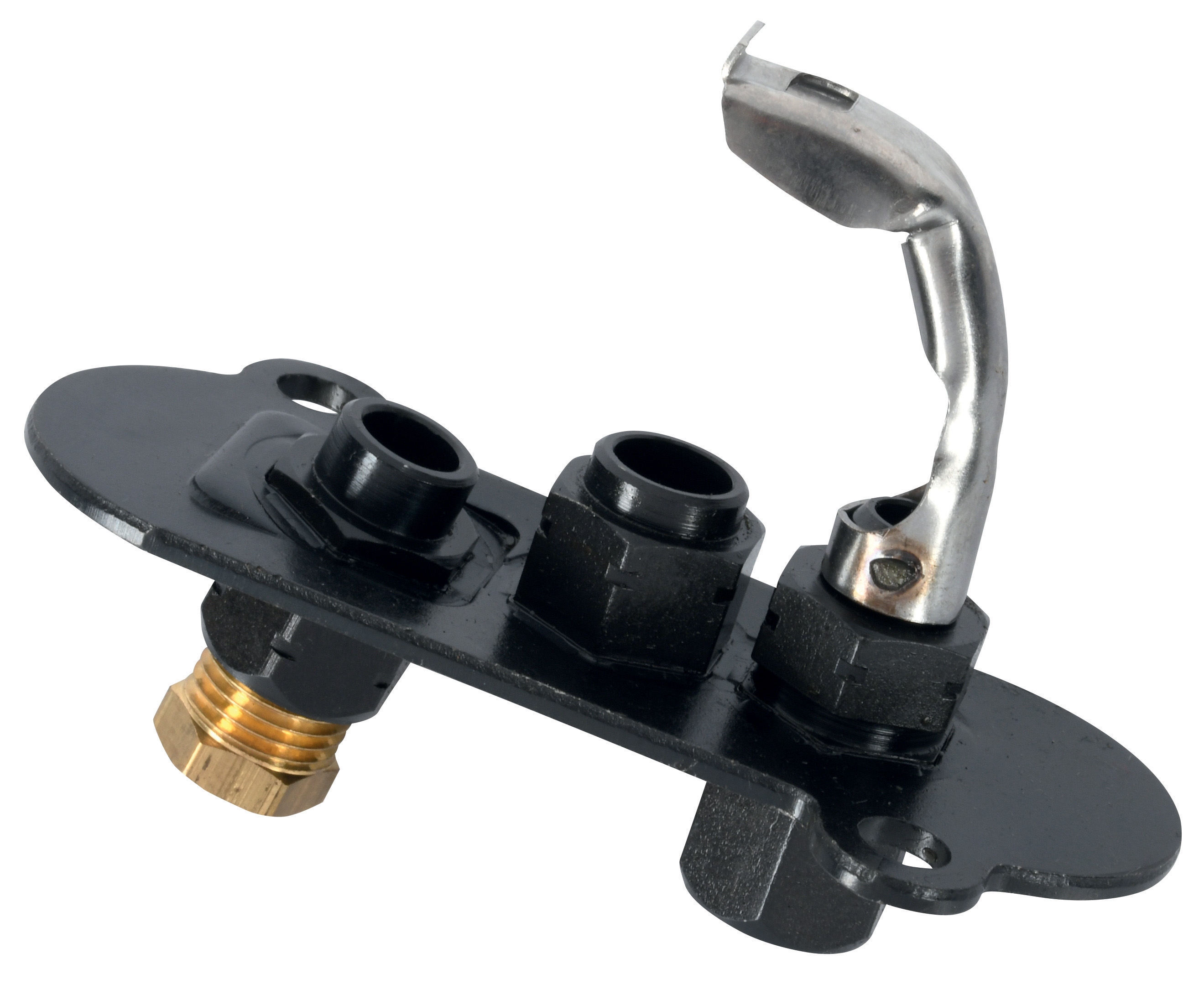
The CBM VCS 1E25R/25R05NNWL3/PPPP/PPPP double solenoid valve represents the industry standard for dual-circuit fuel management. When troubleshooting solenoid performance, begin with voltage verification at the solenoid coil terminals.
Step-by-step solenoid diagnostic approach:
First, verify incoming control voltage using a digital multimeter. Most industrial solenoid valves operate at 120V AC or 24V DC. If voltage is absent, trace back to your relay module and control circuit. If voltage is present but the solenoid doesn't click or hum, the coil has likely failed and requires replacement.
Second, listen for the characteristic solenoid click when the control signal energizes. This click indicates the internal plunger is moving. No click suggests either a failed coil or stuck internal components.
Third, perform a manual override test if your solenoid valve includes a manual override button or pin. Manual overrides allow you to mechanically open the valve without electrical power, helping you determine whether the solenoid itself has failed or whether the problem lies in the control circuit.
Fourth, check for mechanical obstruction. Dirt, corrosion, or debris in the fuel line can prevent solenoid movement. If you suspect contamination, capture a fuel sample and inspect it before the valve inlet. Install fuel strainers upstream of the solenoid if contamination is recurring.
Fifth, verify fuel pressure at the solenoid inlet. Low pressure prevents proper valve operation. Most industrial solenoids require minimum inlet pressure of 0.5 to 2 bar depending on design. Consult your equipment specifications and measure actual pressure during normal operation.
Troubleshooting Pilot Light Ignition Problems
Pilot lights serve as the reliable ignition source for main burner flames. When pilot lights fail or become unstable, the entire burner system can enter lockout, halting operations. Pilot light issues are among the most frequent Controls & Safety problems plant managers encounter.
Typical pilot light failure scenarios:
- Pilot light won't ignite despite spark or hot surface igniter activation
- Pilot light ignites but blows out immediately
- Pilot light flame is weak or poorly positioned
- Intermittent pilot light operation causing nuisance lockouts
- System detects main flame but complains about missing pilot flame signal
The CBM 1-flame pilot light 0.150.082 and CBM pilot light 1 flame 0140026 provide dependable pilot ignition across global industrial applications. These components require proper gas supply, correct air/fuel mixture, and stable flame detection.
Pilot light troubleshooting methodology:
Start by visually confirming pilot flame presence and color during normal operation. Healthy pilot flames typically appear blue with minimal yellow. If you see predominantly yellow flame, the air/fuel mixture is too rich—adjust the air shutter or verify the fuel pressure is within specification.
Second, verify the pilot gas supply by checking fuel pressure at the pilot gas inlet. Pilot systems typically require 0.3 to 1.5 bar depending on orifice size. If pressure is low, check for blockages in the pilot fuel line or verify that the main fuel solenoid is opening properly during pilot ignition mode.
Third, inspect the pilot ignition source. Modern systems use either spark igniters or hot surface igniters. For spark systems, verify electrode gap (typically 2-3mm) and listen for spark sound during ignition attempts. For hot surface systems, confirm the element glows orange when power is applied.
Fourth, examine the flame detection circuit. If the pilot light burns steadily but the control system doesn't recognize it, the flame sensor may be dirty or misaligned. Flame sensors typically use ultraviolet (UV) or infrared (IR) detection. Clean the sensor window carefully with a soft cloth and ensure the sensor directly sees the pilot flame without obstruction.
Fifth, check pilot line routing and connections. Kinked tubes, disconnected fittings, or blocked orifices prevent reliable pilot operation. Trace the complete pilot gas path from the main fuel solenoid through the pilot adjustment valve to the pilot burner tip.
Relay Module and Control Circuit Diagnostics
Relay modules form the electrical intelligence of your Controls & Safety system. These components receive sensor inputs, make logical decisions about safe operation, and send control signals to solenoid valves and ignition systems. Relay failures cascade quickly through dependent systems.
Common relay-related failures:
- System won't energize or immediately locks out after ignition attempts
- Random lockouts without clear fault codes
- Solenoid valves don't respond to control commands
- Pilot or main flame detected but system remains in lockout
- Erratic behavior or intermittent operation
The CBM Relay CM391.2 30.5 1.2 and CBM Base LGK AGM17 provide the control logic and connection infrastructure for modern burner systems. Understanding relay operation helps you distinguish between electrical and mechanical problems.
Relay diagnostic procedure:
First, verify all control power supplies. Relay modules require stable voltage—typically 120V AC, 24V AC, or 24V DC depending on design. Use your multimeter to confirm voltage at the module's power terminals. If power is absent or unstable, investigate the power supply circuit before assuming the relay has failed.
Second, inspect all terminal connections. Corroded, loose, or corroded terminals account for roughly 40% of relay failures we see in the field. Remove and reinstall each terminal, checking for resistance or white/green corrosion deposits. Clean corroded terminals with fine sandpaper and apply dielectric grease to prevent future oxidation.
Third, activate the system and observe relay coil operation. You should hear and feel a distinct click as the relay coil energizes. Multiple clicks or no click suggests either power supply problems or internal relay failure. If the relay clicks but loads (solenoids, igniters) don't respond, the internal relay contacts have likely failed.
Fourth, test safety interlock circuits. Most Controls & Safety systems include interlock inputs from low-water cutoffs, high-limit switches, gas pressure switches, and door safety interlocks. If any interlock is unsatisfied, the relay blocks operation. Trace each interlock circuit to confirm the safety device is functioning and properly connected.
Fifth, document relay behavior over time. If failures are intermittent, the problem is often environmental—temperature extremes, vibration, humidity, or electrical noise. Burners in coastal, industrial, or high-vibration environments need relay modules protected by shielded enclosures and surge protection.
Implementing Preventive Maintenance for Controls & Safety Reliability
Plant managers who invest in systematic preventive maintenance experience 60-70% fewer emergency shutdowns compared to reactive-only approaches. Controls & Safety systems respond well to routine inspection protocols.
Monthly inspection checklist:
- Visually confirm pilot flame during normal operation
- Listen for abnormal solenoid clicking or grinding sounds
- Check fuel pressure at the control block inlet and solenoid outlet
- Verify pilot gas supply pressure and ignition source operation
- Inspect electrical connections for corrosion or looseness
- Test manual override buttons to ensure mechanical backup operation
- Clean flame sensor windows on all detection circuits
- Inspect fuel lines for kinks, cracks, or deterioration
- Verify relay module terminal connections and torque specifications
- Test interlock circuits to confirm safety devices operate independently
- Document system response times and flame establishment delays
- Replace air filters in burner air supply systems
- Inspect and clean fuel strainers
- Service or replace solenoid valve cartridges based on operating hours
- Verify all safety interlocks function during controlled shutdown tests
- Update equipment documentation with current component serial numbers
With over 35 years of industrial equipment distribution experience, 3G Electric understands that Controls & Safety reliability depends on consistent maintenance discipline, quality replacement components, and documented procedures. Having the right parts in stock—including reliable solenoid valves, pilot lights, and relay modules—eliminates downtime from supply delays.
Conclusion
Controls & Safety troubleshooting follows logical diagnostic paths when plant managers understand system architecture and component interaction. Most failures stem from identifiable causes: solenoid valves blocked or electrically failed, pilot lights unstable or unseen by flame sensors, relay modules degraded by corrosion or power supply problems.
By implementing systematic diagnostic procedures and preventive maintenance protocols, you can maintain reliable burner system operation and protect both equipment and personnel. When component replacement is necessary, specifying quality industrial-grade parts ensures compatibility and longevity.
3G Electric has supported plant managers across six continents in solving Controls & Safety challenges. Our technical expertise combined with ready access to proven components helps you return to normal operation quickly and with confidence.