Controls & Safety: Early Detection Through Predictive Diagnostics
Controls & Safety systems form the backbone of industrial equipment reliability, yet many maintenance teams rely on reactive rather than predictive strategies. Drawing on 35+ years of experience distributing industrial equipment across Southeast Asia, 3G Electric has observed that organizations implementing structured predictive diagnostics reduce unplanned downtime by 40-60% while extending component lifecycle significantly.
Predictive diagnostics begins with understanding baseline performance signatures for your specific controls architecture. Unlike generic maintenance schedules, predictive approaches use real-time data collection to identify degradation patterns before catastrophic failure. For flame detection systems—critical safety components in burner control architectures—baseline electrical signal strength, response time, and optical clarity establish the reference against which drift is measured.
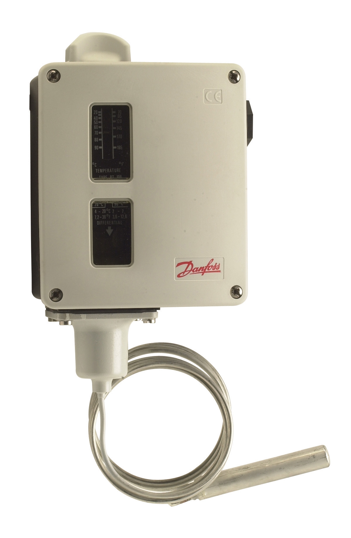
Temperature control devices like the Danfoss Thermostat RT 124 exhibit measurable performance signatures: contact resistance increases gradually before failure, differential setpoint drift occurs over extended operation, and hysteresis margin erosion indicates imminent replacement need. By logging these parameters monthly, maintenance teams establish trend lines that predict replacement windows 4-8 weeks before failure occurs.
Structured Data Collection and Parameter Monitoring
Effective predictive diagnostics requires systematic data collection across four critical measurement categories: electrical performance, thermal response, mechanical integrity, and environmental exposure.
Electrical Performance Metrics:
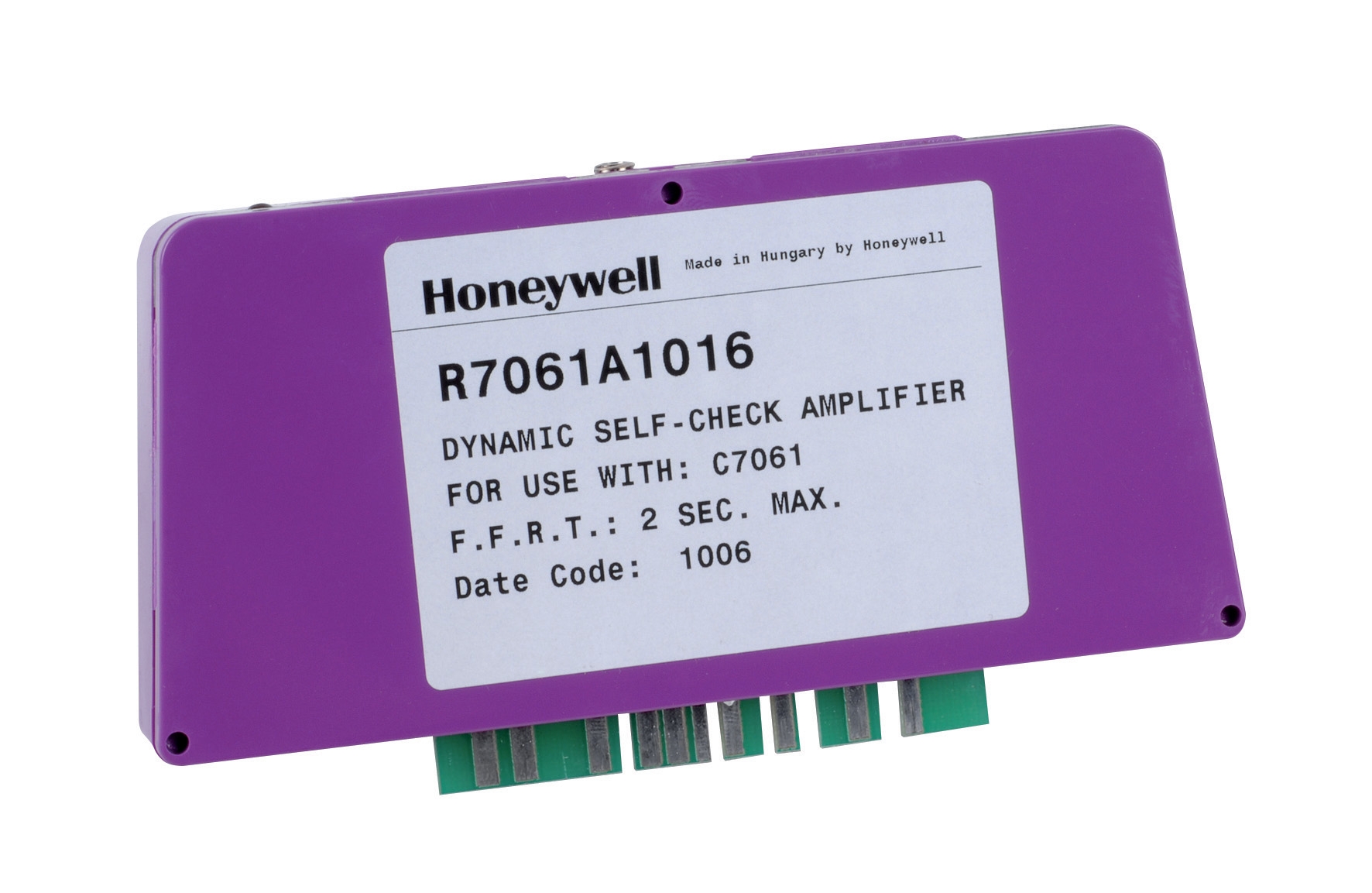
For flame detection amplifiers like the Honeywell Amplifier R 7861 A 1026, establish baseline measurements including:
- Flame signal strength (mV range) at specified reference distances
- Signal-to-noise ratio during normal burner operation
- Response time from ignition spark to flame confirmation (typically 2-4 seconds)
- Shutdown time when flame is interrupted (should be <1 second)
- Leakage current across high-voltage circuits (measured in microamps)
Document these values monthly using calibrated test equipment. Create trending spreadsheets that flag values exceeding ±10% from baseline. Equipment operating in harsh environmental conditions (high humidity, temperature cycling, vibration exposure) may require bi-weekly measurements rather than monthly intervals.
Thermal Response Characteristics:
Thermostats undergo thermal drift as calibration elements age. For devices like the Danfoss Thermostat RT 107, measure:
- Setpoint accuracy at three reference temperatures (low, mid, high range)
- Differential (changeover) consistency—ensure single-pole contacts switch at repeatable intervals
- Neutral zone performance if your application specifies this feature
- Contact resistance at closure point (should remain <0.5 ohms)
Perform these measurements quarterly using a dry-block temperature calibrator. Plot actual setpoint versus nominal setpoint—drift exceeding ±2°C indicates replacement scheduling for the upcoming maintenance window.
Mechanical and Connector Integrity:
Physical degradation often precedes electrical failure. Inspect:
- Connector corrosion or oxidation (particularly in humid Singapore environments)
- Wire strain at connection points
- Housing crack development or seal degradation
- Vibration-induced loosening (critical for equipment exposed to continuous or cyclic vibration)
Documentation of physical conditions creates maintenance history enabling predictive replacement—equipment showing visible corrosion but acceptable electrical performance may be scheduled for replacement before corrosion compromises electrical safety margins.
Preventive Maintenance Protocols Aligned with Component Architecture
Successful preventive maintenance integrates equipment-specific knowledge with operational context. Burner control systems incorporating flame detection (like those using Honeywell Cell C 7044 A 1006 ultraviolet flame detectors) require coordinated maintenance across multiple subsystems.
Pre-Season Commissioning Protocol (Recommended Before Heating Season):
For systems operating seasonally (common in many Singapore industrial facilities), comprehensive commissioning before operation prevents mid-season failures:
1. Flame Detector Inspection and Cleaning: UV sensors accumulate deposits reducing optical transmission. Clean optical surfaces with non-abrasive materials; verify >90% light transmission through calibrated photometer or manufacturer-provided reference standard.
2. Amplifier Functional Testing: Energize the amplifier circuit with no flame present—system should remain in shutdown. Introduce controlled flame (using test lighter or small controlled burner) at specified distance—amplifier should achieve flame confirmation within 4 seconds. Interrupt flame—system should shutdown within 1 second. Document all response times.
3. Thermostat Setpoint Verification: Set thermostats to nominal operating values using dry-block calibrators or furnace-mounted temperature references. Verify changeover occurs within ±1°C of specified setpoint.
4. Control Module Continuity Testing: For systems like the Pactrol CSS01 12 housing control module, verify all relay circuits achieve proper closure and opening, spark generator produces consistent ignition pulses, and safety interlocks (low water cutoff, high temperature limits) respond correctly.
5. System Integration Testing: Run complete burner startup sequence without fuel—verify ignition timing, flame failure response, and shutdown sequence execute properly. Log all timing parameters.
In-Season Monitoring Protocol (Monthly During Operation):
During active operation, monthly monitoring captures early degradation:
- Record flame signal strength and confirm within ±15% of baseline
- Measure thermostat accuracy at current operating setpoint
- Inspect visual condition of connectors and housing for new corrosion or physical damage
- Document any nuisance shutdowns or delayed flame confirmation
- Verify electrical ground integrity and absence of unintended voltage paths
Establish explicit decision criteria for component replacement rather than operating until failure:
- Flame Detectors: Replace if signal strength drops below 80% of baseline, response time exceeds 5 seconds, or any visible optical degradation is observed
- Thermostats: Replace if setpoint drift exceeds ±2°C, contact resistance exceeds 2 ohms, or differential consistency degrades beyond ±1°C
- Amplifiers: Replace if signal-to-noise ratio falls below 8:1, leakage current exceeds 5 microamps, or any environmental exposure (corrosion, physical damage) is evident
- Control Modules: Replace if any relay fails functional testing, spark generation becomes erratic (pulse width variation >10%), or safety interlock response time extends beyond specification
Documentation Systems and Failure Analysis Integration
Maintenance effectiveness depends on systematic knowledge accumulation. Establish documentation practices that connect individual maintenance events to system-level patterns.
Component-Level Records:
Maintain individual files for each critical component containing:
- Installation date and original baseline performance measurements
- Monthly/quarterly measurement logs with trending graphs
- Visual condition photographs (particularly valuable for corrosion documentation)
- Any repairs, adjustments, or component replacements performed
- Ambient operating conditions including humidity, temperature range, and vibration exposure
When components fail or require replacement, conduct root cause analysis that extends beyond the failed component. Example analysis for flame detector failure:
- Did optical degradation (external contamination vs. internal component aging) cause the failure?
- Was the amplifier threshold set appropriately, or was margin eroded prematurely?
- Did environmental conditions (humidity, temperature cycling) accelerate failure compared to baseline equipment in milder environments?
- Were warning signs visible in previous months' diagnostic data that should have triggered earlier replacement?
Document these analyses and share across maintenance team to refine replacement interval estimates and trigger thresholds.
Predictive Model Refinement:
After 12-24 months of data collection, maintenance teams can refine component lifecycle models specific to their operational environment. Initial replacement recommendations (typically manufacturer default intervals of 3-5 years) can be adjusted based on actual degradation rates observed. Equipment operating in harsh conditions may require 2-3 year replacement cycles; equipment in controlled environments may extend to 5-7 years safely.
Practical Implementation for Singapore Industrial Operations
Singapore's tropical climate with high humidity and significant temperature cycling creates accelerated degradation patterns compared to temperate regions. Controls & Safety components experience:
- Rapid connector corrosion requiring more frequent inspection intervals
- Thermal cycling impacts on differential setpoint stability
- Moisture ingress into optical sensor elements affecting flame detection reliability
Maintenance teams should increase monitoring frequency by 50% compared to standard intervals—monthly rather than quarterly measurements for thermostats, bi-weekly rather than monthly for flame detection systems exposed to outdoor air.
Leveraging 3G Electric's regional distribution network and 35+ years of experience, maintenance teams can access replacement components for Danfoss thermostats, Honeywell flame detection systems, Honeywell amplifiers, and Pactrol control modules within 24-48 hours, enabling condition-based replacement strategies rather than emergency spare stocking.
Implementing predictive diagnostics and preventive maintenance protocols transforms maintenance teams from reactive problem-solvers to strategic reliability engineers, maximizing equipment availability while ensuring Safety-critical controls perform within design specifications throughout their operational lifecycle.