Understanding Controls & Safety Through Diagnostic Testing
Controls & Safety in industrial burner systems depend entirely on your ability to detect problems before they become dangerous. Over 35 years as a global equipment distributor, 3G Electric has supported plant managers across Southeast Asia who discovered that most control failures aren't sudden—they develop gradually through sensor drift, contact degradation, and electrical signal loss.
Unlike reactive maintenance that responds to failures, diagnostic testing identifies the root causes of drift and degradation. This approach keeps your systems compliant with local safety standards in Malaysia, Thailand, Vietnam, and Singapore while reducing unplanned shutdowns.
Section 1: Flame Detection System Validation
Why Flame Detectors Drift
Flame detectors—whether ultraviolet sensors like the Honeywell Cell C 7044 A 1006 or infrared types—accumulate optical contamination from combustion byproducts, dust, and thermal stress. Over 6–12 months in humid Southeast Asian environments, signal output can degrade 15–30% without visible exterior damage.
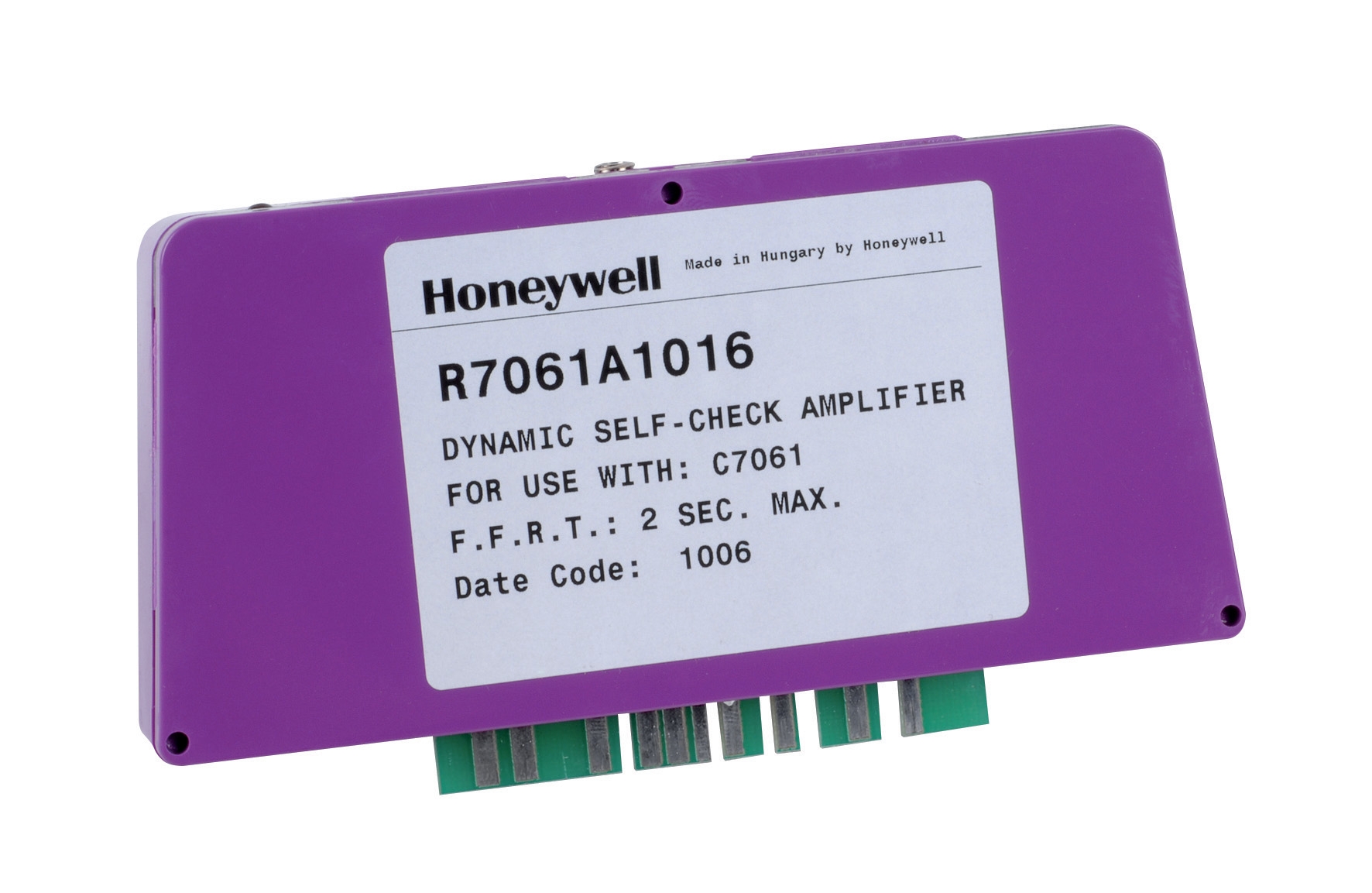
The amplifier response determines whether flame detection remains reliable. The Honeywell Amplifier R 7861 A 1026 processes flame detector signals across temperature extremes (-40°C to 60°C) and vibration stress (0.5 g continuous). If the amplifier doesn't receive a clean signal from a drifting detector, response time increases—and response time is a safety-critical parameter.
Practical Diagnostic Protocol
Monthly visual inspection:
- Check detector lens for soot, condensation, or thermal crazing
- Wipe with lint-free cloth and calibrated solvent (isopropyl alcohol)
- Document lens transparency on a reference card
- Use a handheld flame simulator or controlled test burner
- Measure detector output voltage at a fixed flame position (typically 1–2 meters)
- Compare to baseline (usually 2–4 VDC for UV detectors)
- Action threshold: If signal drops below 70% of baseline, schedule cleaning or replacement
- Record measurements in a trending log; flag detectors with downward slope over consecutive tests
- Simulate flame signal ramp-up using a signal generator
- Confirm amplifier recognizes flame presence within ≤4 seconds
- Verify flame failure lockout triggers within ≤5 seconds of signal loss
- Document on test worksheet; retain for compliance audits
- Send detectors and amplifiers to manufacturer service center
- Verify optical sensitivity and electronic response specifications
- Replace gaskets and seals degraded by thermal cycling
Section 2: Thermostat Calibration and Differential Verification
Temperature Control Drift in Tropical Climates
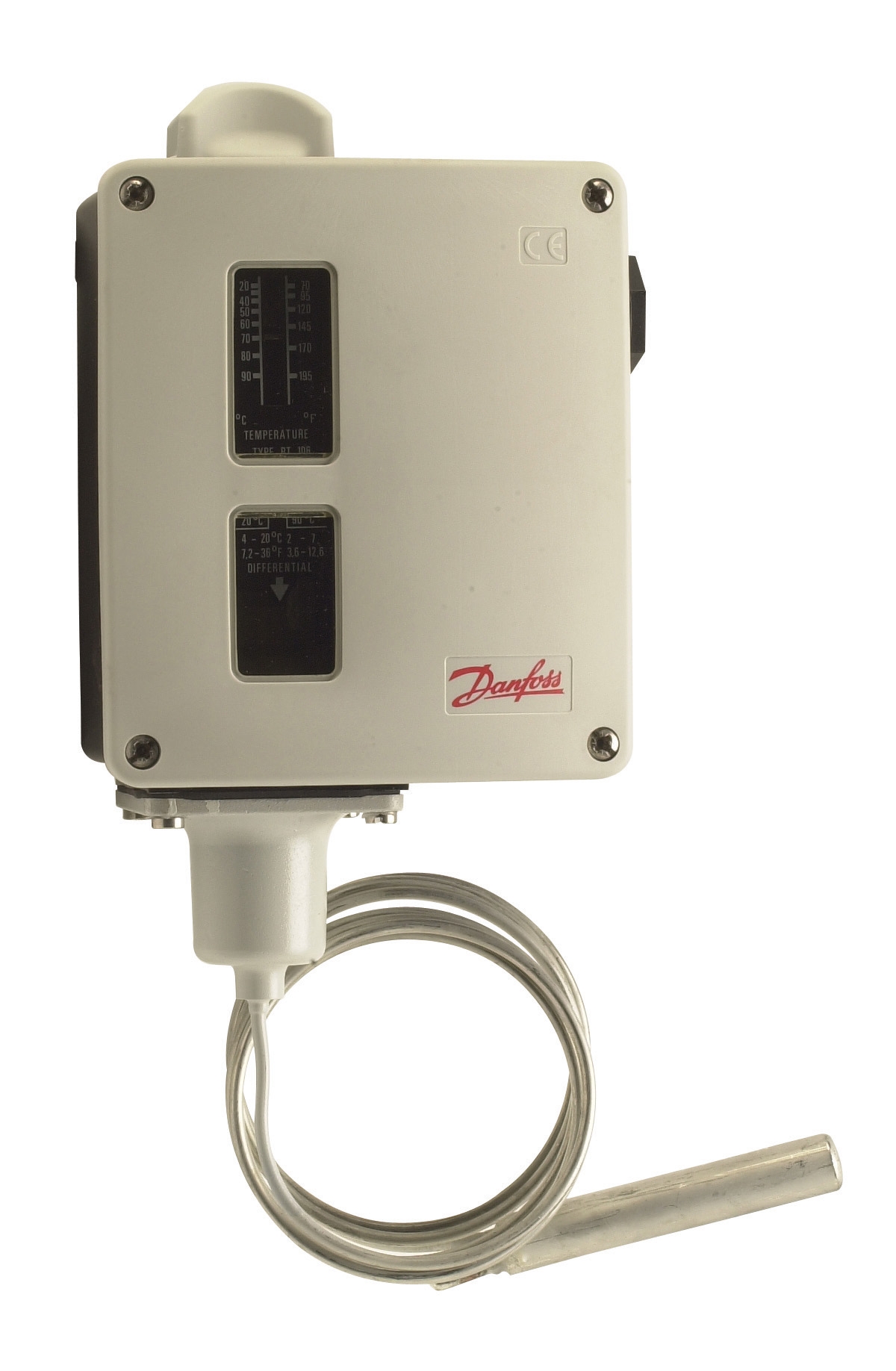
Thermostats like the Danfoss RT 124 and Danfoss RT 107 use bulb-actuated mechanisms where a temperature-sensitive fluid expands and contracts to open or close electrical contacts. In Southeast Asia's high-humidity environment, thermal cycling combined with vibration from equipment operation causes:
- Contact resistance increases (leading to erratic switching)
- Differential settings drift (setpoint moves 2–5°C off calibration)
- Neutral zone collapse (reduced hysteresis causes chatter and rapid on/off cycling)
Rapid cycling damages solenoid valves, relay contacts, and ignition systems—and consumes energy inefficiently.
Diagnostic Testing Procedure
Quarterly setpoint verification:
- Place thermostat and reference thermometer in a calibration bath or ambient chamber
- Slowly raise temperature at 2°C per minute
- Record temperature at which thermostat contact closes ("make" temperature)
- Continue raising temperature; record temperature at which contact opens ("break" temperature)
- Calculate differential: Break – Make temperature
- Compare differential to nameplate specification (typically ±3°C tolerance)
- If differential exceeds tolerance or is asymmetrical, thermostat requires replacement
- Disable manual override; allow thermostat to control system for one complete heating cycle
- Log thermostat switching points alongside process temperature readings from an independent sensor
- Verify on-temperature matches setpoint ±2°C
- Confirm off-temperature remains within differential range
- If process overshoots setpoint by >5°C, replace thermostat
- Check for mineral deposits or discoloration inside the bulb (indicates internal corrosion)
- Inspect wiring terminals for oxidation or loose connections
- Verify mounting orientation matches nameplate (some models are position-sensitive)
Section 3: Burner Control Module Sequencing and Safety Interlock Testing
The Control Module as a Safety Controller
Integrated burner control modules like the Pactrol CSS01 12 combine timed relay functions, flame relay logic, and ignition sequencing in a single enclosure. In small-to-medium forced-air and atmospheric burners (up to 60 kW), this module is the "safety system"—it enforces the correct sequence of air purge, ignition, and burner fuel valve opening.
A malfunctioning control module can:
- Skip air purge (resulting in explosive fuel accumulation)
- Allow fuel valve to open without ignition (creating unburned gas release)
- Fail to shut down on flame loss (dangerous for appliances and personnel)
Diagnostic Testing Sequence
Monthly operational sequence test:
- Manually initiate a start cycle from the thermostat or control switch
- Observe and document timing of each event:
- Delay period (typically 30–60 seconds for air purge)
- Ignition spark or pilot flame ignition
- Burner fuel valve opening
- Flame detection confirmation
- Compare to nameplate sequence diagram
- If any step is missing, out of order, or excessively delayed, mark the control module for replacement
- Start the burner normally and confirm stable flame
- Temporarily block the flame sensor (simulate flame loss) or use manufacturer's test button
- Control module should de-energize fuel valve within ≤5 seconds
- Measure de-energization time with a stopwatch; document
- If shutdown exceeds 10 seconds, replace control module
- Test any door interlocks, pressure switches, or external safety switches wired into the control circuit
- Manually trip each interlock (e.g., open access door if equipped with door switch)
- Confirm burner shuts down within ≤3 seconds
- Re-enable interlock and verify normal restart capability
- Document all interlock response times
- De-energize control module and measure resistance of relay coils (should read 500–2,500 Ω depending on coil rating)
- Inspect solder joints on circuit board for cracks or cold joints
- Measure AC supply voltage at module terminals; confirm ±10% of nameplate (typically 120 VAC or 230 VAC)
- If voltage is out of tolerance, investigate upstream power quality
- Look for burn marks, discoloration, or component corrosion inside the enclosure
Section 4: Preventive Maintenance Scheduling for Southeast Asian Operations
Climate and Environmental Challenges
Southeast Asia's tropical and subtropical climate accelerates equipment degradation:
- High humidity (60–90%) causes corrosion and electrical leakage
- Temperature swings (22–35°C ambient daily) stress thermal sensors and solder joints
- Industrial dust and salt spray (especially near coasts) contaminate optical sensors and contacts
- Intermittent power quality in some regions damages sensitive electronics
Maintenance Schedule by Component Type
Flame detectors and amplifiers (e.g., Honeywell Cell C 7044 + Honeywell R 7861):
- Weekly: Visual lens inspection
- Monthly: Lens cleaning if dust visible
- Quarterly: Signal amplitude test
- Semi-annual: Amplifier response time verification
- Annual: Factory recalibration and seal replacement
- Replace every 5 years (or earlier if recalibration fails)
- Quarterly: Setpoint verification in calibration bath
- Semi-annual: Field load testing
- Annual: Visual inspection for corrosion
- Replace every 5–7 years or when differential exceeds tolerance
- Monthly: Operational sequence observation
- Quarterly: Flame loss shutdown test
- Semi-annual: Interlock verification
- Annual: Electrical continuity and voltage measurement
- Replace every 10 years or if sequence errors appear
- Quarterly: Listen for abnormal solenoid chatter or ignition spark degradation
- Semi-annual: Measure solenoid coil resistance and spark gap
- Replace solenoid coils every 7–10 years; replace electrodes annually if spark voltage is erratic
Documentation and Compliance
Create a maintenance logbook (physical or digital) with:
- Equipment serial numbers and installation dates
- Test results and measurement dates
- Technician name and signature
- Corrective actions taken
- Component replacement dates and part numbers
Retain records for minimum 3 years (meets most Southeast Asian regulatory requirements). This documentation demonstrates due diligence if a safety incident investigation occurs and provides evidence for warranty claims.
Key Takeaways for Plant Managers
1. Flame detectors degrade gradually—optical contamination reduces signal 15–30% over 6–12 months. Quarterly signal testing catches drift before it affects safety response.
2. Thermostat differential drift is common in humid climates—verify setpoint and differential quarterly using a reference thermometer. Erratic switching indicates replacement is needed.
3. Control module sequencing must be tested under load—observe a complete start cycle monthly and confirm flame shutdown occurs within 5 seconds of flame loss.
4. Predictive maintenance reduces unplanned downtime—systematic testing catches problems 4–8 weeks before catastrophic failure, giving you time to source replacement components without emergency shipping costs.
5. Documentation is your safety defense—maintain a detailed logbook proving regular diagnostic testing and corrective action. This protects your facility, your team, and your legal standing.
For more than 35 years, 3G Electric has supplied replacement components and diagnostic tools to plant managers across Southeast Asia. We carry flame detectors, thermostats, control modules, and amplifiers in stock, with technical support available to help you develop a diagnostic testing plan tailored to your equipment and environment.