Understanding Controls & Safety Diagnostics in HVAC Burner Systems
Controls & Safety systems represent the operational intelligence of modern industrial burners—but only when their components function reliably. For HVAC contractors working across Singapore's demanding industrial environment, the ability to quickly diagnose control failures separates profitable service calls from costly callbacks. With over 35 years of experience distributing industrial heating equipment, 3G Electric has supported thousands of contractors in mastering diagnostic protocols that reduce downtime and ensure system compliance.
The challenge contractors face is not merely identifying that a control component has failed, but understanding why it failed and whether the failure indicates a deeper system issue. A malfunctioning flame detector, for example, might signal inadequate combustion air, burner head contamination, UV tube degradation, or amplifier signal processing errors—each requiring different corrective actions.
Flame Detector and Amplifier Diagnostic Workflows
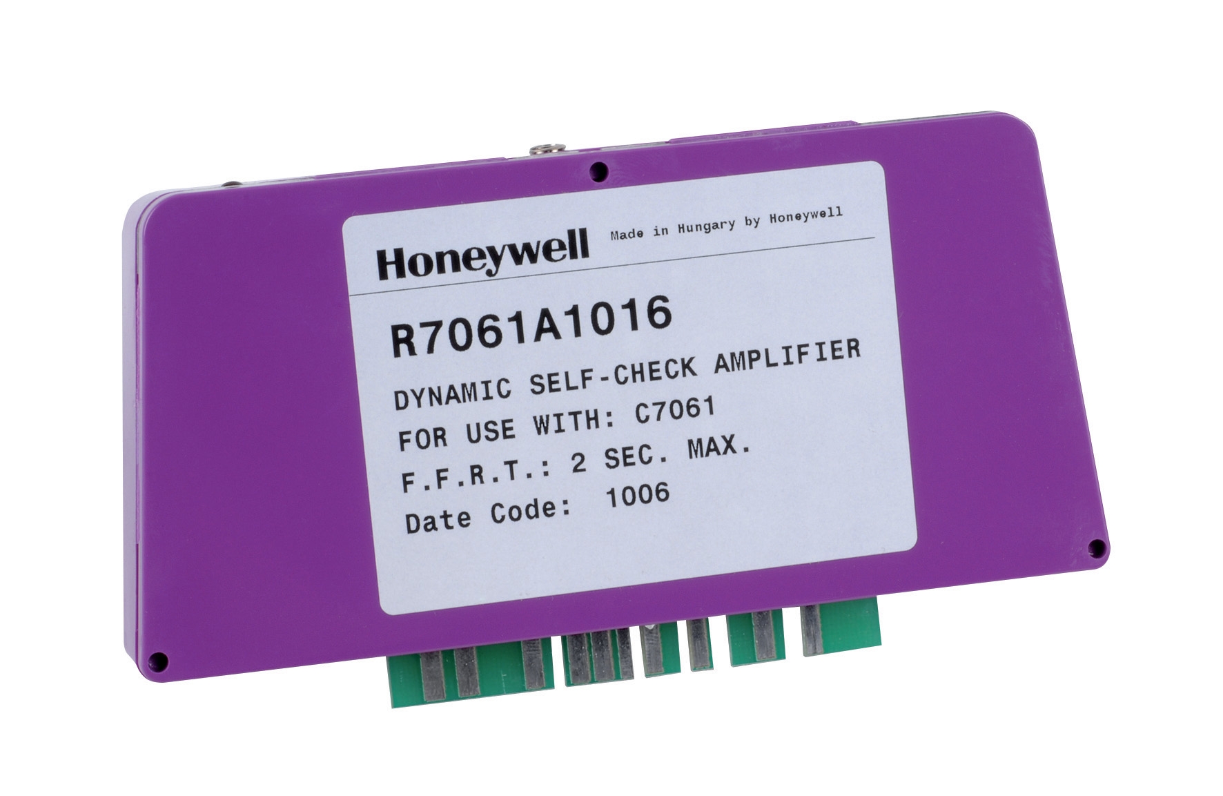
Flame detection systems are the safety backbone of any burner installation. The Honeywell Cell C 7044 A 1006 ultraviolet flame detector and Honeywell Amplifier R 7861 A 1026 work as an integrated pair, and diagnosing them requires a systematic approach.
Visual Inspection and UV Tube Assessment
Begin with non-invasive checks before applying electrical testing. Remove the UV flame detector tube from its holder (if design permits) and inspect the quartz window for contamination—carbon deposits, oil residue, or combustion byproducts significantly reduce UV light transmission. Singapore's high-humidity tropical climate accelerates corrosion on tube contacts and housing connectors; inspect for green or white oxidation. Clean the quartz window with lint-free cloth and appropriate solvent; never touch the glass directly with bare fingers as skin oils block UV wavelengths.
Check tube contact integrity. The Honeywell Cell C 7044 A 1006's mechanical connection must seat firmly in its holder. Loose contacts generate intermittent flame-out signals that trigger unwanted shutdowns. Verify the tube rotates slightly within the holder without binding—excessive tightness can crack the ceramic tube.
Electrical Continuity and Resistance Testing
With the burner off and power disconnected, use a digital multimeter to measure resistance across the UV tube leads. A functional tube typically reads between 1 MΩ and 10 MΩ—the exact range depends on light conditions and tube age. Measure in complete darkness; ambient room light affects readings. Resistance below 0.5 MΩ indicates internal tube failure and requires replacement. If resistance reads infinite (no continuity), check whether the tube is properly seated and contact surfaces are clean.
For the Honeywell Amplifier R 7861 A 1026, apply similar continuity testing to amplifier input and output terminals before power-up. This amplifier operates across -40°C to 60°C and tolerates 0.5 g continuous vibration, but mechanical stress can damage solder connections on circuit boards. Vibration-related failures often manifest as intermittent flame-out during high-speed air fan startup.
Powered Signal Testing
Once mechanical integrity is confirmed, apply power and observe the amplifier's response to light stimuli. In a controlled environment, shine a bright flashlight toward the UV tube and confirm the amplifier's output relay energizes or de-energizes (depending on logic type). This validates that the optical-to-electrical signal path functions. Repeat this test in the dark to confirm the relay de-energizes when UV stimulus is absent.
Measure voltage at the amplifier's output terminal during both lit and dark conditions. For a typical normally-open flame relay, output voltage should transition between 0V (no flame) and supply voltage (flame detected). If voltage remains static, suspect amplifier failure or wiring discontinuity. Use a clamp ammeter to verify load draw at the output relay coil—normal operation typically draws 50–150 mA depending on relay type.
Thermostat Validation and Temperature Sensing Diagnostics
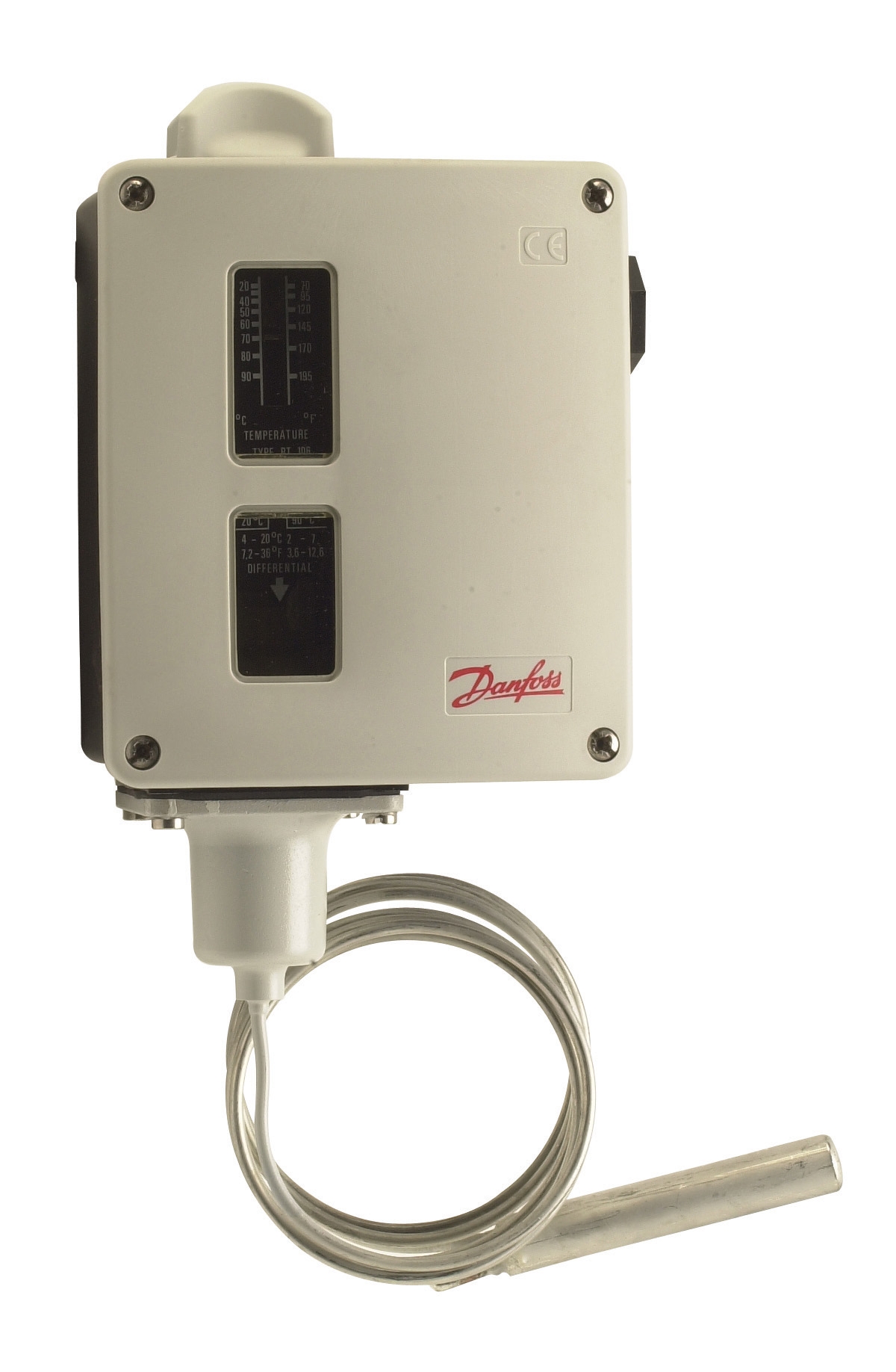
Thermostats like the Danfoss RT 124 bulb-actuated thermostat and Danfoss RT 107 form the temperature control loop in HVAC burner systems. Unlike electronic sensors, bulb-actuated thermostats contain liquid-filled sensing elements that expand or contract with temperature—and this mechanical action drives electrical contacts.
Physical and Sensory Inspection
Examine the thermostat bulb for physical damage—dents, cracks, or discoloration of the stainless steel housing compromise sensing accuracy. In Singapore's corrosive salt-air environments near coastal industrial zones, surface oxidation is common. Slight surface pitting is acceptable; deep corrosion or pitting that penetrates the bulb wall requires replacement. Gently manipulate the capillary tube connecting the bulb to the thermostat body; it must flex without kinking. A kinked capillary breaks internal pressure equalization and causes erratic temperature response.
Inspect electrical contacts visually for pitting, carbon buildup, or discoloration. Light surface oxidation can be cleaned with contact cleaner and a soft brush; heavy pitting indicates thousands of electrical switching cycles and suggests the contact set is nearing end of life. Measure contact resistance using a multimeter—should be below 0.1 Ω when contacts are closed.
Temperature Response Testing
Perform a controlled immersion test to validate temperature-sensing linearity. Place the thermostat bulb in a temperature-controlled water bath with an independent calibrated thermometer. Slowly increase temperature and record the switching setpoint. For the Danfoss RT 124, which features adjustable differential, verify that the switching hysteresis (dead band) matches the design specification—typically 2–5 K for HVAC applications. Repeat the test during cooling (decreasing temperature) to confirm contact closure/opening follows the calibrated setpoint within ±1 K tolerance.
If the thermostat exhibits sluggish response or delayed switching, suspect impaired thermal conductivity in the bulb-to-capillary connection. Ensure the bulb is fully immersed; partial immersion introduces sensing errors. After testing, allow the thermostat to cool naturally rather than removing it from the bath immediately—rapid temperature changes can separate the liquid charge from dissolved gases, creating air pockets that degrade response accuracy.
Integrated Control Module Diagnostics and Sequencing Validation
Modular control units like the Pactrol CSS01 12 housing control module integrate multiple safety and sequencing functions—timed relay, flame relay, and electronic spark generator—in a single enclosure. Diagnosing integrated modules requires understanding the sequence logic and validating each subsystem independently.
Power Supply and Voltage Rail Testing
Measure primary and secondary supply voltages at the control module terminals before energizing loads. The Pactrol CSS01 12 is designed for atmospheric and small forced-air burners up to 60 kW; verify supply voltage matches nameplate specifications (typically 120V or 240V AC). Measure ripple voltage on DC rails using an oscilloscope—ripple should not exceed 5% of nominal DC voltage. Excessive ripple indicates capacitor degradation in the power supply section, which cascades into unreliable solenoid valve switching and flame detector signal noise.
Timed Relay Function Verification
The timed relay manages pre-purge and ignition timing sequences. Apply power and confirm the relay energizes after the specified delay (typically 3–5 seconds for pre-purge cycles). Use a stopwatch to measure actual timing; modules operating in Singapore's high-temperature industrial environments may drift from nominal values due to thermal expansion affecting RC timer components. Timing drift exceeding ±10% of setpoint warrants replacement.
Trigger the flame detection circuit (manually if no burner is running) and confirm the timed relay de-energizes when flame signal is received. The control module must lock out and prevent re-ignition attempts if flame is lost unexpectedly—test this by simulating flame signal loss and confirming the module enters a lockout state that requires manual reset via a pushbutton or power cycle.
Spark Ignition Generator Output Verification
The electronic spark generator produces high-voltage pulses for pilot light ignition. Spark output is difficult to measure directly without specialized equipment, but functional testing is practical: apply power and confirm audible spark at the electrode (a distinctive clicking sound at 20–30 Hz). Lack of audible spark combined with pilot light non-ignition indicates generator failure or wiring discontinuity to the electrode.
Measure voltage at the spark electrode terminal using a high-impedance multimeter or oscilloscope. A functional generator produces 5–10 kV peak voltage. Verify adequate clearance (typically 3–4 mm) between the electrode and burner frame—excessive gap increases ignition difficulty; inadequate clearance allows sparks to jump to unintended paths, reducing ignition reliability.
Common Failure Modes and Root Cause Analysis
Intermittent Flame-Out During Load Fluctuations
This failure pattern typically indicates marginal flame detection. The UV tube may be contaminated with combustion products accumulated over weeks of operation. Clean the quartz window and re-test. If flame-out persists, measure the flame signal amplitude at the amplifier input—inadequate signal (below the amplifier's minimum sensitivity threshold) means the burner combustion intensity is marginal. Increase fuel pressure slightly or verify adequate combustion air supply. In some cases, the amplifier's gain setting requires adjustment; consult the manufacturer's technical documentation for your specific module.
Thermostat Contact Chatter and Oscillation
Rapid opening/closing of thermostat contacts (audible as buzzing) indicates the setpoint is unstable or the temperature sensing element is responding to vibration. Verify the thermostat is mounted securely on the pipe or duct wall—vibration-induced chatter causes excessive electrical contact erosion. Ensure the bulb is fully immersed in the medium being controlled; partial immersion in air creates large temperature swings due to poor thermal transfer. If chatter persists after mechanical securing, the thermostat may have internal separation or capillary tube damage, requiring replacement.
Failure to Ignite After Extended Shutdown
After several days without operation, some control modules fail to complete the ignition sequence. Suspect capacitor leakage in the timed relay circuit; capacitors in tropical humid climates like Singapore deteriorate faster due to moisture ingress and elevated ambient temperatures. Measure capacitor voltage before operation—should be zero. If residual voltage remains after power-down for 5+ minutes, the capacitor's discharge path is compromised and the capacitor requires replacement. This is a common failure pattern in modules operating continuously at elevated ambient temperatures (>35°C).
Best Practices for Sustainable Diagnostic Procedures
Maintain a diagnostic log for each burner system you service. Record ambient temperature during testing, component serial numbers, measured values (resistance, voltage, response times), and any adjustments made. This historical record allows you to detect slow degradation trends—for example, flame detector response time increasing by 50 ms per year indicates UV tube degradation before failure occurs.
Invest in appropriate test equipment: a digital multimeter capable of measuring high resistance (>10 MΩ) for UV tube testing, an oscilloscope for analyzing control signal waveforms, and a calibrated thermometer for thermostat validation. Over 35 years, 3G Electric has observed that contractors who maintain diagnostic discipline—testing rather than guessing—achieve higher first-time fix rates and build stronger customer relationships through transparent reporting.
When ordering replacement components like Danfoss RT 124 thermostats or Honeywell flame detectors, verify compatibility with your control module's logic and voltage specifications. Cross-reference the original equipment with the component datasheet; mismatched voltage ratings or contact logic types create intermittent failures that are difficult to diagnose in the field.
Document the commissioning state of the system (setpoints, response times, voltage readings) and perform annual validation testing to detect drift before operational failure occurs. This preventive discipline is especially critical for safety-critical components like flame detectors and interlocking controls, where failure can create hazardous conditions.