Introduction: Controls & Safety Installation and Compliance in Singapore
Procurement engineers managing industrial burner systems in Singapore face a critical responsibility: ensuring that Controls & Safety installations meet both local regulatory requirements and international safety standards. With Singapore's stringent workplace safety regulations and adoption of ISO, EN, and IEC standards, proper installation and compliance verification are non-negotiable.
Drawing on 35+ years of industrial equipment distribution experience, 3G Electric has supported countless procurement teams through the complexities of Controls & Safety system deployment. This guide provides a structured approach to installing, verifying, and certifying Controls & Safety components—ensuring your burner control systems achieve full regulatory compliance while maintaining operational safety and reliability.
Section 1: Pre-Installation Assessment and Component Selection
Before any Controls & Safety component is installed, procurement engineers must conduct a comprehensive pre-installation assessment. This phase determines which control and safety components are appropriate for your specific application and ensures compatibility with existing systems.
Key Assessment Steps:
- Application Analysis: Document burner type (gas, oil, or dual-fuel), thermal capacity (kW/BTU rating), operating mode (continuous or intermittent pilot), and existing control architecture.
- Regulatory Mapping: Cross-reference Singapore Standards (SS), Machinery Safety Directive requirements, and industry-specific codes (marine, food processing, petrochemical) applicable to your facility.
- SIL and Performance Level Requirements: Determine Safety Integrity Level (SIL) and Performance Level (PL) requirements based on risk assessment. For most Singapore industrial burners, SIL 2-3 is standard.
- Certification Verification: Confirm that candidate components carry relevant certifications—EN 746-2 (burner safety), EN 1854 (pressure switches), FM, UL, or GOST-TR depending on your supply chain and insurance requirements.
For a medium-capacity gas burner in Singapore requiring SIL 3 operation, you might specify:
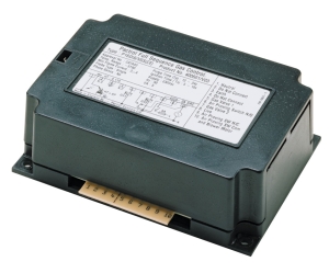
- Kromschroder Relay BCU 570WC1F1U0K1-E (EN 746-2 compliant, supports direct and pilot ignition)
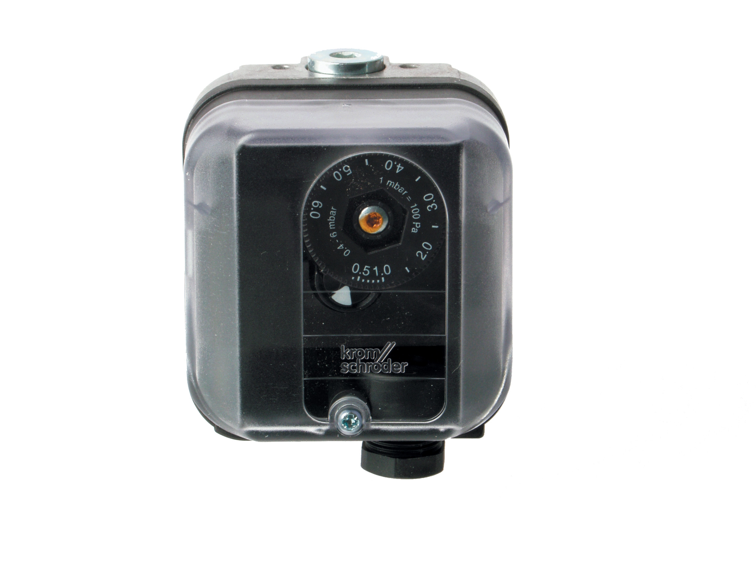
- Kromschroder Pressure switch DG 50U/6 (SIL 3, EN 1854 certified)
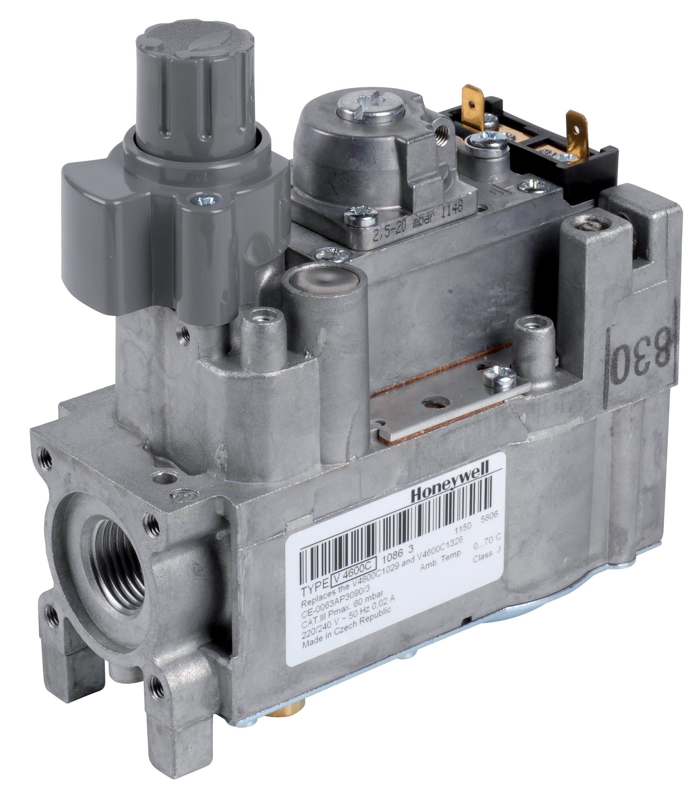
- Honeywell Gas block VK 4105 C 1041 U (modulating pressure control)
This combination provides redundant safety monitoring while maintaining precise gas flow control.
Section 2: Installation Procedure and Safety Protocols
Proper installation is foundational to Controls & Safety system reliability. Singapore's Workplace Safety and Health Act requires documented installation procedures and qualified personnel supervision.
Installation Prerequisites:
- Equipment Shutdown: De-energize the burner system completely. Lock out and tag out (LOTO) all energy sources—electrical, gas, and pilot light supplies.
- Component Inspection: Visually inspect all Controls & Safety components for shipping damage, manufacturing defects, or environmental contamination. Document findings in your installation log.
- Piping and Wiring Verification: Verify that gas lines, pressure tubing, electrical conduits, and signal wiring are correctly sized, routed, and secured according to design drawings.
When installing safety relays like the Siemens Relay LFL 1.622, follow these steps:
1. Mounting: Secure the relay in an IP54-rated control enclosure away from vibration sources and thermal extremes. Singapore's humid climate requires moisture-resistant enclosures.
2. Electrical Connections: Terminate 24 VDC control power, ignition output, flame supervision input, and interlock contacts according to wiring diagrams. Use color-coded terminals and label every connection.
3. Flame Monitoring Setup: Connect flame detection sensors (UV or ionization type) with shielded cable to prevent noise pickup. Verify sensor positioning and line-of-sight to pilot or main flame.
4. Air Damper Integration: If using controlled air damper capability, wire the damper actuator to the relay output and verify full-stroke operation (0-10 VDC modulation range).
5. Pressure Switch Integration: Connect the Kromschroder Pressure switch DG 50U/6 with appropriate gauge pressure calibration for your application.
Gas Block Installation (Modulating Systems):
The Honeywell Gas block VK 4105 C 1041 U requires precise pilot connection tuning:
- Connect M8 x 1 pilot line from burner to pilot port
- Connect M5 pressure feedback line from proportional valve to feedback port
- Verify operating temperature remains within -5 to 140°F range; use insulation in high-temperature burner rooms
- Test modulation response by observing pressure feedback signal (4-20 mA) across load range
The Pactrol Housing P 16 DI CE 400601/V23 operates at 230V with high-voltage output (12 kV, 10 MJ):
- Mount in a dedicated enclosure with appropriate high-voltage safety clearances
- Route HV cable separately from control signal wiring to prevent cross-talk
- Install spark plug connectors with dry-disconnect safety interlocks
- Verify ignition timing pulse matches burner ignition electrode configuration
Before formal commissioning, perform preliminary functional checks:
- Energize 24 VDC control power and verify all indicator lights and relay status signals
- Confirm flame monitoring sensors respond to light stimulus (UV) or electrode resistance changes (ionization)
- Actuate manual override buttons and verify safe-state responses
- Simulate fault conditions (flame loss, pressure drop, high temperature) and log relay shutdown response times
Section 3: Compliance Verification and Certification Testing
Singapore's regulatory environment requires documented evidence of Controls & Safety compliance. Procurement engineers must coordinate verification testing aligned with Singapore Standards, EN standards, and facility insurance requirements.
Pre-Commissioning Compliance Checklist:
- Component Certifications: Collect and file EN 746-2, EN 1854, FM, UL, or AGA certificates for all control and safety components. Verify certification scope matches your application.
- Design Safety Documentation: Complete a Functional Safety Assessment (FSA) confirming SIL 2-3 architecture, failure mode analysis, and safe-state verification.
- Installation Records: Maintain dated installation logs with photographs, component serial numbers, and technician sign-off.
- Calibration Certificates: Obtain calibration data for pressure switches and temperature sensors, traceable to Singapore's National Measurement Institute (NMI) standards.
The Kromschroder DG 50U/6 and similar pressure switches must be verified against design setpoints:
1. Setpoint Confirmation: Using a precision pressure calibrator (0.25% accuracy minimum), raise system pressure slowly until the switch trips. Record switching pressure and compare against design setpoint ±3% tolerance.
2. Hysteresis Testing: Lower pressure back down and record reset point. Hysteresis should fall within manufacturer specification (typically 10-20% of setpoint).
3. Response Time Measurement: Document pressure switch electrical response time (typically <100 ms) and mechanical latching time using a data logger.
4. Certification: Have testing performed by an ISO 17025 accredited lab with traceable standards. In Singapore, providers like SAMSA (Singapore Accreditation Service) maintain lists of approved calibration laboratories.
Relay and Safety Controller Verification:
For the Siemens LFL 1.622 and Kromschroder BCU 570WC1F1U0K1-E, verify:
- Flame Supervision Response: Introduce pilot flame and confirm relay "lock-in" within 2-3 seconds; extinguish flame and verify shutdown within 4-5 seconds.
- Safety Shutdown Tests: Remove flame supervision signal and confirm all gas solenoid valves de-energize within safe response times (typically <2 seconds).
- Interlock Logic Verification: Test all permissive interlocks (air pressure switches, high-temperature cutouts, manual isolation valves) and confirm that any single fault condition triggers safe shutdown.
- Electrical Continuity and Insulation: Measure control wiring insulation resistance (minimum 10 MΩ for dry circuits) using a 1000 VDC megohmmeter.
The Pactrol Housing P 16 DI CE ignition module requires:
- Spark Plug Gap and Polarity: Verify spark plug electrode gap (typically 3-4 mm) and polarity alignment with module terminals.
- Ignition Timing Pulse: Using an oscilloscope, confirm ignition pulse frequency (typically 2-3 pulses per second during startup phase) and voltage magnitude (10-12 kV peak).
- Thermal Cycling Test: Energize the module for 15 minutes and measure temperature rise. Verify operating temperature remains below safe limits and thermal protective devices function if temperature exceeds setpoint.
Before delivering the burner control system to the customer, 3G Electric recommends a comprehensive FAT with documented results:
- All calibration certificates and test results filed
- Flame suppression test (safety shutdown within safe response times)
- Full load and part-load operational cycles
- Fault injection tests (simulated component failures)
- Environmental stress screening (thermal cycling if applicable)
Section 4: Post-Installation Compliance Documentation and Maintenance
Regulatory compliance does not end at commissioning. Procurement engineers must establish documentation systems and preventive maintenance protocols to maintain Controls & Safety system integrity throughout operational life.
Essential Documentation:
- Burner Safety Data Sheet (BSDS): Create a facility-specific BSDS documenting all control and safety functions, setpoints, response times, and fault procedures.
- Maintenance Log: Record all inspections, calibrations, component replacements, and functional tests with dates and responsible personnel.
- As-Built Drawings: Update P&ID (Piping and Instrumentation Diagrams), electrical schematics, and control logic diagrams to reflect installed configuration.
- Training Records: Document operator and maintenance technician training on Controls & Safety system operation, fault diagnosis, and emergency procedures.
Based on Singapore Standards and international best practices:
- Weekly: Visual inspection of control enclosure for water ingress, overheating, or component degradation.
- Monthly: Flame detector testing (verify response to light stimulus), manual valve operation, and pressure gauge reading comparison.
- Quarterly: Pressure switch calibration verification using calibrated gauges; fuel supply filter inspection.
- Annually: Complete functional safety assessment; relay and safety controller diagnostic testing; ignition module spark gap inspection and replacement if needed.
- Every 2-3 Years: Professional recalibration of pressure switches and sensors by ISO 17025 accredited laboratories; replacement of worn electrode tips in spark plugs or flame detectors.
Schedule annual independent audits (internal or third-party) to verify:
- All Components retain valid certifications and traceability documentation
- Maintenance logs are current and complete
- Functional safety assessment remains valid; any system modifications are documented and re-assessed
- Staff training records demonstrate competency
- Any defects or deviations are recorded and corrective actions tracked to closure
Maintain records for potential Singapore Workplace Safety and Health inspection:
- Risk assessment and Functional Safety Assessment documentation
- Equipment certification and compliance records
- Maintenance and calibration logs
- Incident and near-miss reports related to Controls & Safety functions
- Training attendance and competency assessments
Conclusion
Installation and compliance verification of Controls & Safety systems in Singapore industrial burner operations demands systematic attention to technical detail, regulatory requirements, and documentation rigor. By following the assessment, installation, verification, and maintenance protocols outlined in this guide, procurement engineers can ensure that burner control systems achieve full regulatory compliance while delivering reliable, safe operation.
3G Electric's 35+ years of experience supporting industrial equipment procurement has demonstrated that disciplined Controls & Safety practices—starting at the specification phase and extending through the operational lifecycle—significantly reduce safety incidents, unplanned downtime, and regulatory exposure. Whether you are specifying Kromschroder safety relays, pressure switches, Siemens flame supervision units, gas control blocks, or ignition modules, the systematic approach to installation and verification outlined here provides the foundation for dependable, compliant burner control system performance.