Understanding Controls & Safety Diagnostic Architecture
Effective Controls & Safety systems do more than prevent accidents—they provide visibility into equipment health before catastrophic failure occurs. For plant managers operating burner systems across multiple facilities, diagnostic capability is often the difference between scheduled maintenance and emergency shutdowns.
Three major component categories dominate industrial burner Controls & Safety: temperature regulation devices (thermostats), flame detection systems, and integrated control modules that orchestrate the complete ignition and safety sequence. Each presents distinct diagnostic challenges and opportunities.
At 3G Electric, our 35+ years distributing industrial equipment have shown us that plants investing in diagnostic-rich controls reduce unplanned downtime by 30-40% compared to facilities relying on basic on/off functionality. This article examines how to evaluate diagnostic capability when selecting Controls & Safety components for your facility.
Thermostat Diagnostic Capabilities vs. Field Complexity
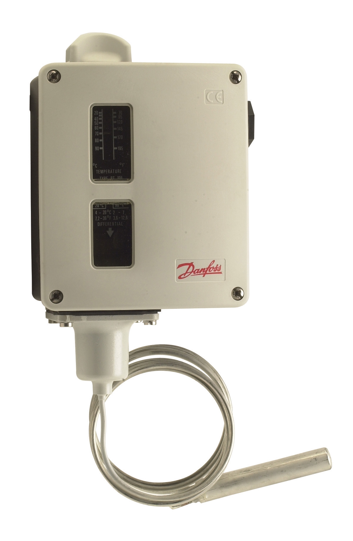
Thermostats form the foundation of temperature-based safety logic in HVAC and process heating applications. The Danfoss RT 124 and Danfoss RT 107 represent two approaches to temperature monitoring with different diagnostic profiles.
The RT 124 (bulb-actuated, single-pole changeover) provides indirect diagnostics through contact position feedback. When your burner fails to ignite despite reaching setpoint temperature, the changeover contact's position tells you whether the thermostat itself is functioning. However, pinpointing the failure requires external verification—measuring the liquid-filled bulb's response to actual system temperature takes time your maintenance team may not have available.
The RT 107 (universal changeover design) offers similar contact-based diagnostics but with broader application flexibility. In both devices, true diagnostic value emerges only when integrated with monitoring infrastructure that logs contact state transitions. Without this logging layer, you're performing reactive troubleshooting after the system fails.
Practical diagnostic advantage: Thermostats with documented response curves and adjustable differential settings (both RT models include this) allow your team to validate proper operation during commissioning. Record baseline response times in your CMMS—when response slows by 15-20%, you've identified a thermostat requiring replacement before it causes operational failure.
Cost implication: Thermostat diagnostics are primarily manual and dependent on technician skill. A plant without systematic temperature logging cannot exploit the diagnostic richness these components offer.
Flame Detection Systems: Active vs. Passive Diagnostic Information
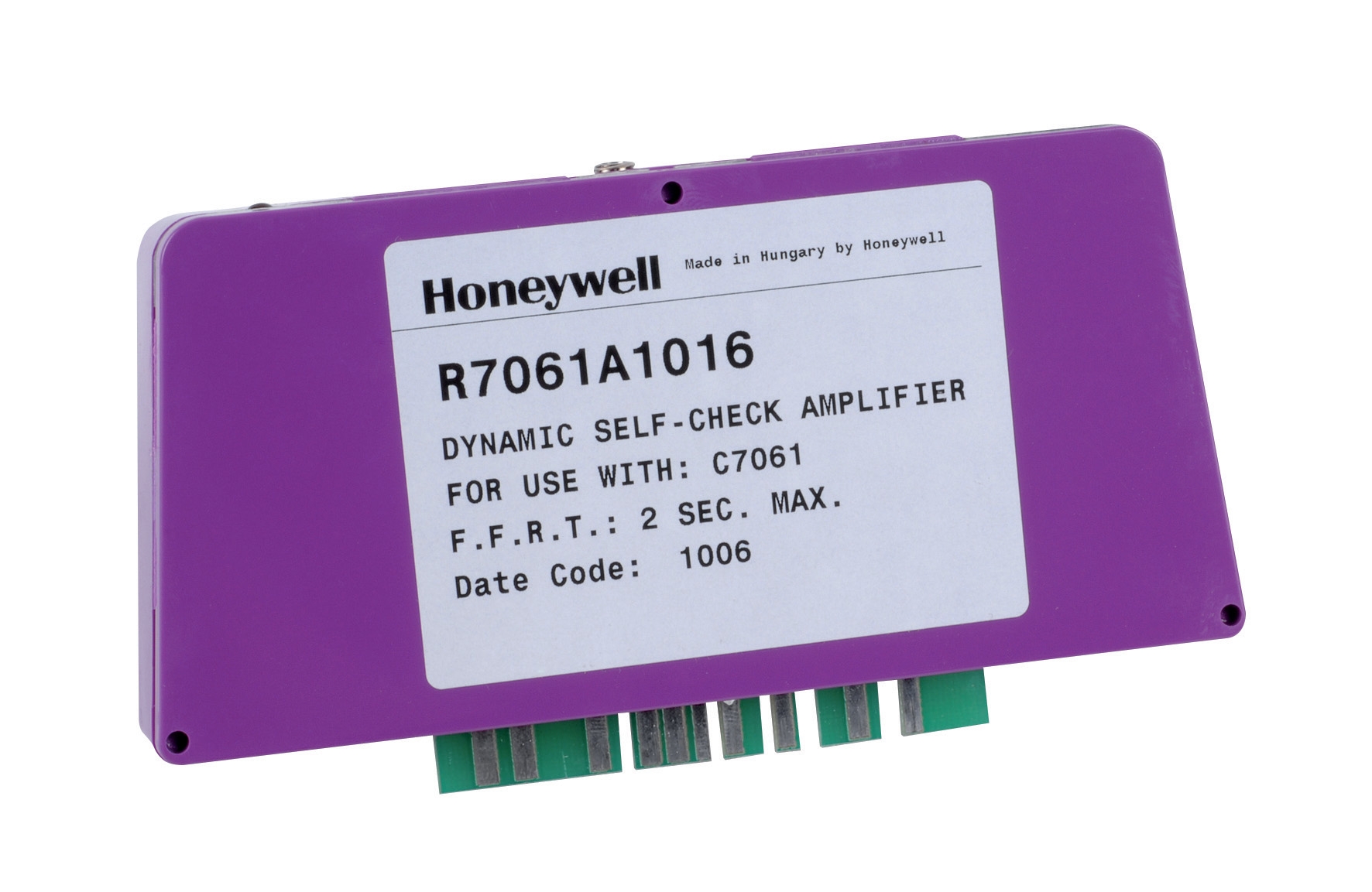
Flame detectors represent a leap forward in diagnostic capability compared to thermostats. The Honeywell Cell C 7044 A 1006 ultraviolet flame detector and its companion Honeywell R7861A 1026 amplifier together create an active feedback loop that reports flame status in real time.
UV flame detection advantages:
- Direct signal output: The detector doesn't simply report "flame present" or "flame absent"—it generates an analog voltage proportional to UV radiation intensity. This gives you signal strength data that indicates flame robustness.
- Amplifier diagnostic reporting: The R7861A amplifier operates across -40°C to 60°C while tolerating 0.5g continuous vibration. Its design includes internal validation of detector signal integrity. When amplifier output goes zero despite correct ignition sequence, you know the detector itself has failed—not the ignition system.
- Predictive health indicator: Declining signal strength from an otherwise functioning detector often precedes complete failure. Plants monitoring amplifier output voltage can schedule detector replacement during planned maintenance windows rather than experiencing unplanned shutdowns.
Practical advantage: Implement analog signal monitoring on your flame detection circuit. Most building management systems (BMS) or programmable logic controllers (PLCs) can log this data. When your detector shows signal decline, you transition from reactive ("why did the burner suddenly shut down?") to predictive maintenance ("schedule detector replacement next Wednesday").
Control Module Integration: Unified Diagnostics Across Multiple Functions
The Pactrol CSS01 12 control module represents a different diagnostic philosophy. Rather than distributing diagnostic responsibility across separate thermostat, detector, and amplifier components, integrated modules consolidate logic and reporting.
The CSS01 integrates three critical functions:
- Timed relay – ignition sequencing and run-time monitoring
- Flame relay – response to detector signal
- Electronic spark generator – ignition energy delivery
- Sequence validation: The module confirms that ignition energy fired, the detector saw flame within expected timeframe, and burner ran for intended duration. Deviations from this sequence trigger specific fault codes.
- Simplified troubleshooting logic: Rather than testing thermostat, then detector, then amplifier, then ignition transformer—your technician reads one fault code that pinpoints the failure category.
- Compliance documentation: For facilities subject to safety audits, integrated modules provide audit trails showing that each ignition cycle completed proper safety checks.
The CSS01 supports atmospheric and small forced-air burners up to 60 kW—its diagnostic capability scales directly with application complexity. Larger burner systems may exceed the module's built-in sensing capacity.
Building Your Diagnostic Strategy: Integration Framework
Temperature monitoring (thermostat) diagnostics work best when you:
- Record baseline response times during commissioning and store in your maintenance documentation
- Implement daily log checks comparing thermostat response to outdoor/ambient temperature trends
- Flag any response degradation exceeding 20% as requiring technician investigation
- Continuous analog signal monitoring—either through your BMS, dedicated flame signal monitor, or PLC
- Documentation of normal signal voltage range during healthy operation
- Alert thresholds set 15-20% above zero, catching declining detector performance before complete failure
- Annual detector cleaning and recalibration to maintain baseline signal integrity
- Logging of fault codes from each ignition cycle
- Trend analysis of error frequency—increasing errors indicate early component degradation
- Documented test procedures for validating module response to simulated thermostat and flame detector inputs
- Verification that sequence logic completes within manufacturer specifications
The most effective Controls & Safety strategies layer these three diagnostic approaches. A failing thermostat might be masked by flame detection reliability until thermal runaway occurs. A weakening flame detector might go unnoticed in integrated modules until the module finally denies ignition permission. Redundant diagnostic visibility prevents this scenario.
Practical Implementation for Multi-Facility Operations
For plant managers operating multiple burner systems across different facilities, standardizing on components with compatible diagnostic signals yields significant advantages:
- Technician training investment multiplies: Your team learns one diagnostic protocol applicable across all installations
- Spare parts inventory optimization: You stock detectors, thermostats, and amplifiers known to work together reliably
- Data collection becomes actionable: Comparing diagnostic trends across facilities reveals which environmental conditions (humidity, vibration, thermal cycling) stress components most
3G Electric has supported thousands of plant operations across 35+ years by helping managers establish this diagnostic infrastructure. Your initial investment in monitoring capability—BMS integration, signal logging, and alert configuration—typically returns value within the first year through reduced emergency service calls alone.
Summary: Diagnostic Capability as Selection Criterion
When evaluating Controls & Safety components, resist the temptation to choose based purely on purchase price. The Danfoss RT 124 thermostat and Honeywell flame detector represent proven diagnostic capability—but only if you build the infrastructure to capture and act on that diagnostic information.
Your selection framework should answer:
1. What diagnostic data can this component generate?
2. How will I capture that data (manual logging, automated monitoring, or integrated module reporting)?
3. What action will I take when diagnostics indicate potential failure?
4. How does this component's diagnostic capability integrate with other Controls & Safety devices in my system?
Plants that answer these questions systematically see dramatic improvements in burner reliability, compliance documentation, and ultimately, plant profitability.