Understanding Controls & Safety in Modern Burner Systems
Controls & Safety components form the backbone of reliable industrial burner operations, and procurement engineers face a critical challenge: selecting individual components that actually work together seamlessly. Rather than evaluating each component in isolation, forward-thinking organizations specify complementary controls and safety devices that integrate into cohesive systems.
At 3G Electric, our 35+ years of experience distributing industrial equipment globally has taught us that component compatibility matters as much as individual performance specifications. We've observed that many equipment failures stem not from defective components, but from mismatched Controls & Safety systems that create operational friction points.
This article examines how to build robust Controls & Safety architectures by understanding the interplay between dual solenoid valve systems, relay logic platforms, and pilot light configurations. We'll focus on practical procurement strategies that reduce commissioning delays and minimize field failures.
Double Solenoid Valves: The Control Foundation for Dual-Line Systems
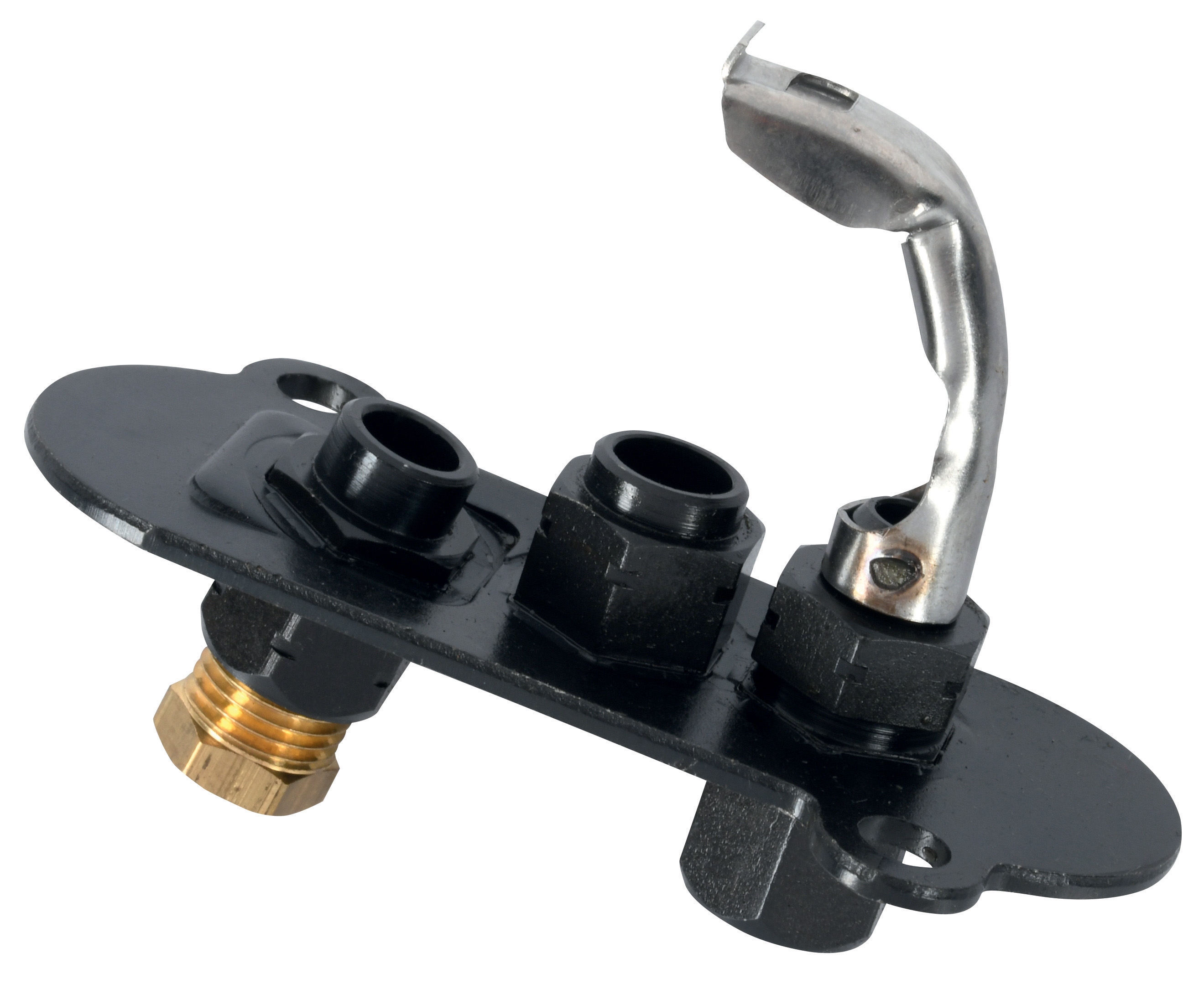
Double solenoid valve configurations represent a critical control point in modern burner safety systems. The CBM VCS 1E25R/25R05NNWL3/PPPP/PPPP double solenoid valve provides independent control of two fuel supply lines, enabling sophisticated safety logic that single-valve systems cannot achieve.
From a procurement engineering perspective, double solenoid valves offer several distinct advantages:
Redundancy and Fail-Safe Operation
Dual solenoid configurations allow for "fail-safe" logic where each solenoid controls a separate fuel path. If one solenoid fails (opens or closes unexpectedly), the second solenoid remains functional. This architectural approach provides inherent safety without requiring complex external logic systems. Procurement engineers should understand that this redundancy is built into the valve design itself—you're not adding external failsafes to a single valve.
Independent Staging and Flow Control
Many modern burner systems require staged combustion, where fuel delivery increases or decreases in steps to match load demands. Double solenoid valves enable this without external splitter blocks or complex piping arrangements. One solenoid can control low-fire fuel delivery while the second manages high-fire increments. This simplifies your bill of materials and reduces potential leak points.
Pressure-Rated Actuation for High-Capacity Systems
The CBM VCS series handles pressurized fuel delivery up to 25 bar, which accommodates both low-pressure gas systems and pressurized fuel oil lines. When specifying Controls & Safety components, confirm that your solenoid valve rating matches your fuel system pressure—undersized valves create backpressure issues that affect flame quality and safety sensor response times.
Integration with Relay-Based Control Logic
Double solenoid valves serve as the execution point for relay logic platforms. Rather than viewing solenoids and relays as separate specifications, procurement engineers should coordinate their selections: the relay contact rating must match the solenoid coil amperage, and the solenoid voltage (typically 24V DC in industrial applications) must align with your control circuit design.
Relay Platforms and Pilot Light Integration: Coordinating Controls & Safety Logic
Relay systems translate sensor inputs and operator commands into mechanical actions at the solenoid valve. The CBM Relay CM391.2 30.5 1.2 operates as a modular relay within larger control assemblies, while the CBM Base LGK AGM17 provides the mounting and electrical infrastructure.
Procurement engineers often treat relays and their bases as commodity items, but this approach undermines Controls & Safety performance. Here's why coordination matters:
Electrical Load Matching
Relay contact ratings (measured in amperes and watts) must accommodate your solenoid valve coil specifications. A common procurement mistake occurs when engineers specify a relay base rated for 16A but pair it with solenoids drawing 20A at startup (inrush current). The contact burns out within weeks, creating intermittent solenoid failures that field technicians struggle to diagnose. Always cross-reference relay contact capacity against solenoid coil specifications, factoring in inrush current multipliers (typically 1.2-1.5x steady-state current).
Modular Base Architecture for Future Expansion
The LGK AGM17 base system uses modular relay sockets, allowing you to add or reconfigure relays without redesigning your entire control circuit. This flexibility proves invaluable when burner systems require upgrades—you can swap relay modules rather than replacing entire control panels. When procuring Controls & Safety systems, this modularity reduces long-term capital costs and minimizes downtime during equipment evolution.
Time-Delay and Interlock Functionality
Relay platforms enable sophisticated control sequences: time-delay relays prevent solenoid chattering (rapid opening/closing), while interlocking logic ensures pilot lights are established before main fuel delivery begins. These safety sequences are mechanical—they don't depend on software or microcontrollers, which makes them inherently reliable in harsh industrial environments.
Integration with Pilot Light Confirmation Circuits
Relay logic platforms provide the control pathway for pilot light monitoring. The relay receives feedback from your flame-sensing circuit (whether optical, infrared, or thermoelectric) and uses this information to control solenoid valve energization. If the pilot light signal fails, the relay de-energizes the solenoid, shutting down fuel delivery. This feedback loop creates a true "safety-critical" system where fuel delivery cannot occur without confirmed pilot ignition.
Pilot Lights: The Verification Point for Controls & Safety Systems
Pilot lights serve a deceptively simple function: they ignite burner fuel and provide a measurable flame signal for safety confirmation. However, pilot light selection directly impacts system reliability and maintenance costs.
The CBM 1-flame pilot light 0.150.082 and CBM Pilot light 1 flame 0140026 represent different design philosophies that affect Controls & Safety performance differently.
Flame Signal Stability and Sensor Response
Pilot light design influences flame signal characteristics—the brightness, spectral content, and flicker frequency that flame sensors detect. A poorly designed pilot can produce unstable signals that cause relay chatter or false shutdowns. When procuring pilot lights, examine the combustion chamber design, fuel atomization characteristics, and thermal stability features. Better pilots maintain consistent flame geometry even as fuel pressure or ambient temperature fluctuates.
Ignition Energy Requirements
Pilot lights require reliable ignition to establish themselves. Some designs tolerate wider ignition spark ranges and fuel pressure variations, while others demand precise conditions. Procurement engineers should coordinate pilot light ignition requirements with your spark ignition system specifications—undersized ignition systems create intermittent pilot lighting failures that appear random but actually reflect poor component matching.
Maintenance Accessibility and Nozzle Geometry
Pilot light nozzles accumulate carbon deposits over time, especially in applications with poor fuel quality or incomplete combustion. Select pilot designs with accessible nozzles and robust cleaning procedures. Some pilot configurations allow field nozzle replacement without full disassembly, reducing maintenance labor. Document these maintenance requirements in your procurement specifications—they directly impact total cost of ownership.
Thermal Stability in Variable Load Applications
Burner systems with wide load ranges create thermal stress on pilot lights. High-fire operation generates heat that can affect pilot stability during subsequent low-fire operation. Procurement engineers should verify that selected pilot lights maintain stable performance across your burner's full operating range, not just at design point conditions.
Integrated System Procurement Strategy: Beyond Component Selection
Successful Controls & Safety system procurement requires thinking beyond individual component specifications. Your procurement strategy should address system-level integration:
Compatibility Matrix Development
Create a compatibility matrix during the procurement planning phase that documents how components interact:
- Solenoid valve voltage and coil amperage (including inrush current)
- Relay contact ratings and time-delay specifications
- Pilot light ignition requirements and flame signal characteristics
- Interface between flame detection sensors and relay logic platforms
This matrix prevents mismatches that appear acceptable on individual datasheets but cause failures in integrated operation.
Standardization for Maintenance Efficiency
Organizations operating multiple burner systems benefit from standardizing Controls & Safety component selections across similar applications. This reduces spare parts inventory, enables cross-training of maintenance personnel, and simplifies procurement administration. Working with experienced distributors like 3G Electric—our 35+ years of global operations provide access to extensive application precedents—helps identify standardized component combinations proven in comparable environments.
Field Commissioning Coordination
Allocate adequate commissioning time to verify Controls & Safety system function before production operation. Test solenoid valve response timing, relay switching sequences, and pilot light ignition reliability under actual operating conditions. Component selection documents should include commissioning checklists that field engineers follow to verify proper integration.
Supply Chain Resilience Planning
Controls & Safety components experience varying lead times and supply availability. Procurement engineers should identify critical path items (typically solenoid valves and relay bases) and maintain buffer inventory for unplanned replacements. Coordinate procurement timing to avoid situation where one missing component delays an entire system installation.
Conclusion: From Component Selection to System Integration
Controls & Safety system reliability depends on thoughtful integration of complementary components rather than isolated selection of high-performing parts. Procurement engineers who coordinate double solenoid valve specifications, relay platform configurations, and pilot light characteristics create systems that operate predictably, require minimal field troubleshooting, and achieve their intended safety objectives.
At 3G Electric, our experience distributing industrial controls and safety equipment across global markets reinforces this integration principle. We've observed that organizations prioritizing component compatibility achieve lower commissioning costs, fewer field failures, and better long-term operational efficiency than those treating Controls & Safety procurement as a series of independent component purchases.
