Introduction: Why Thermal Load Matching Matters in Industrial Combustion
Burners & Combustion systems represent one of the largest energy expenditures in modern manufacturing plants. Yet many facility managers operate with undersized or oversized burners, accepting poor efficiency as normal operating cost. In Singapore's competitive industrial environment, thermal load matching—selecting a burner with capacity precisely calibrated to your facility's actual heat demand—directly influences your bottom line.
Incorrect burner sizing creates cascading problems: undersized units run at maximum capacity with reduced turn-down ratio, oversized units cycle frequently, and both scenarios waste fuel and accelerate component wear. With 35+ years of experience distributing industrial combustion equipment across Asia-Pacific operations, 3G Electric has helped hundreds of plant managers optimize their thermal infrastructure through scientific load analysis and proper burner selection.
Section 1: Calculating Your Facility's True Thermal Load
Understanding Heat Demand Profiles
The foundation of effective burner sizing is accurate thermal load calculation. Unlike simpler equipment selection, combustion systems require plant managers to account for dynamic operating conditions rather than single nameplate ratings.
Start by mapping your facility's thermal demand across a typical operating cycle:
- Peak load scenarios: Maximum simultaneous heat demand (e.g., all production lines running, steam generation at full capacity)
- Average operating load: Typical daytime production thermal requirements
- Minimum operating load: Night shifts, maintenance periods, seasonal variations
- Startup thermal requirements: Energy needed to bring equipment from cold to operating temperature
- Recovery demand: Heat needed after brief production interruptions
For example, a food processing plant in Singapore's industrial estates might require:
- 630 kW peak load during peak production hours (8am–3pm)
- 450 kW average sustained load across 16-hour operation
- 180 kW minimum load during night production
- 800 kW transient demand for 15 minutes during shift changeover heating
This profile immediately tells you that a single fixed-capacity burner is inappropriate. You need either a modulating burner with turn-down capability or a dual-burner system with low/high staging.
Load Calculation Methodology
Conduct a detailed energy audit using these inputs:
1. Process heating requirements: Sum all equipment requiring heat (kettles, steam generators, dryers, autoclaves). Document their rated capacities and actual duty cycle percentages.
2. Thermal losses: Calculate heat loss through insulation, piping, and equipment surfaces. For poorly insulated systems, losses can represent 15–25% of total demand.
3. Efficiency factor: Modern burners operate at 85–95% thermal efficiency depending on combustion air preheating and recovery systems. Factor this into your calculation.
4. Seasonal variation: Singapore's tropical climate minimizes heating load variation, but supply chain facilities with imported materials and export processing may have cyclical demand patterns.
Calculation formula:
Required Burner Capacity = (Total Process Heat Demand + Thermal Losses) / Burner Efficiency
For a facility requiring 500 kW actual heat output with 10% system losses and 90% burner efficiency:
Required Capacity = (500 + 50) / 0.90 = 611 kW
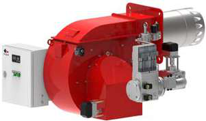
This means selecting a burner rated for approximately 630 kW—matching the FBR GAS XP 60/2 CE TC EVO burner specifications, which delivers 116–630 kW in two-stage modulating operation.
Section 2: Matching Burner Type to Your Thermal Profile
Single-Burner vs. Multi-Burner Configurations
Your load profile directly determines system architecture:
Single Modulating Burner (appropriate when):
- Load variation is moderate (peak load ≤ 2× minimum load)
- Turn-down ratio capability of 4:1 to 8:1 meets your minimum load requirement
- Equipment design supports variable heat input without damage
- Downtime for maintenance is acceptable
The FBR GAS XP 60/2 CE TC EVO two-stage gas burner exemplifies this approach, offering modulating control from low-fire to full capacity with integrated damper control for air-fuel ratio optimization.
Dual-Burner Configuration (appropriate when):
- Load variation exceeds 5:1 (common in batch processing, shift-based operations)
- Redundancy is required for critical continuous processes
- Faster response time to load changes improves product quality
- Equipment efficiency improves with discrete sizing (e.g., one 300 kW + one 150 kW rather than single 450 kW)
For heavy oil applications with extreme load variation, consider the FBR KN 1300/M TL EL dual-fuel burner offering 1700–11,500 Mcal/h range with modulating stages.
Fuel Type Considerations in Singapore's Industrial Context
Singapore's location creates specific fuel availability patterns:
- Natural gas: Via piped city supply (most urban industrial estates), offering clean combustion and simplest control integration
- LPG: Backup option with marginally higher combustion control complexity and fuel cost premium
- Heavy fuel oil: Common in process industries, marine applications, and facilities with backup heating capacity
- Dual-fuel burners: Increasingly popular for redundancy and cost optimization, switching between natural gas and oil based on price/availability
Gas burners typically operate at tighter air-fuel ratios (±3% oxygen deviation) compared to oil burners (±5–6% deviation). This affects burner control system selection. The Siemens LFL 1.622 safety control unit supports all fuel types with integrated UV flame monitoring and ionization flame detection, making it suitable for flexibility.
Section 3: Control System Integration for Load Matching
Burner Control Architecture
Once you've sized the burner, the control system must reliably execute load matching without compromising safety. This requires:
1. Accurate Load Sensing
- Temperature sensors in heated medium (steam, water, or product)
- Pressure transducers monitoring system operating point
- Integrated feedback to burner control unit for proportional response
- Air damper modulation maintaining stoichiometric ratios
- Fuel valve staging (low-fire, modulating, high-fire)
- Flame monitoring at all operating points
- Pressure switches preventing operation outside safe envelopes
- Flame detection confirming ignition before fuel flow continues
- Automatic shutdown on fault conditions
The Kromschroder DG 50U/6 pressure switch (SIL 3, Performance Level e) integrates into safety loops, protecting against low/high pressure conditions that indicate load mismatch or system faults. It meets all relevant standards for Singapore industrial applications (EN 1854, FM, UL certifications).
Relay and Control Unit Selection
For medium-capacity gas burners with modulating capability, the Kromschroder BCU 570WC1F1U0K1-E burner control relay provides direct ignition and intermittent/continuous pilot control, compliant with EN 746-2 and EN 676. This unit automatically adjusts burner response based on load demand, preventing overshooting and fuel waste.
Integration points:
- Connect temperature feedback from process equipment to control input
- Link pressure switch output for low-load shutdown logic
- Configure modulating valve response curve matching your specific equipment
- Verify flame monitoring circuit before commissioning
Section 4: Practical Implementation and Performance Verification
Commissioning Thermal Load Matching
After burner installation, conduct formal commissioning to confirm load matching:
1. No-Load Baseline Test
- Record idle fuel consumption (pilot light only)
- Measure baseline oxygen percentage in flue gas
- Document all control unit parameter settings for future reference
- Increase facility load in 10–20% increments
- Record fuel flow, air damper position, and oxygen percentage at each level
- Verify that modulation response is smooth (no hunting or oscillation)
- Confirm that control unit automatically adjusts air-fuel ratio
- Run at maximum nameplate load for minimum 30 minutes
- Induce rapid load changes (simulate production startup/shutdown)
- Confirm burner responds within 5–10 seconds without overshooting
- Verify flame monitoring remains active throughout
- Confirm pressure switch trips at design setpoints (±3% accuracy)
- Test flame loss detection: burner should shut down within 4–5 seconds
- Verify control unit reset sequence and interlock logic
Ongoing Performance Monitoring
Load matching performance degrades over time due to:
- Fouling of heat exchanger surfaces (reduces effective heat transfer)
- Burner nozzle deposits affecting spray pattern and combustion efficiency
- Air damper mechanical wear changing modulation curve
- Sensor drift (temperature, pressure transducers lose calibration)
Implement quarterly monitoring:
Monthly checks:
- Visual inspection of burner flame color (should be even, light blue)
- Record fuel consumption at standard load point (e.g., 75% capacity)
- Measure oxygen percentage in flue gas
- Professional flue gas analysis (CO, NOx, smoke density)
- Pressure switch calibration verification
- Control unit parameter review and adjustment if needed
- Complete burner disassembly and cleaning
- Nozzle inspection and replacement if deposits present
- Sensor calibration or replacement
- Full safety system functional test
Tracking these metrics helps you detect efficiency drift before it becomes expensive. A 3–5% fuel consumption increase over six months typically indicates fouling or control system drift—both correctable with planned maintenance costing far less than premium fuel waste.
Conclusion: Strategic Value of Proper Burner Sizing
Burners & Combustion systems operating with correctly matched thermal load deliver measurable financial returns:
- Fuel cost reduction: 8–15% typical savings through elimination of oversizing and cycling losses
- Extended equipment life: Reduced thermal stress and part replacement frequency
- Improved product quality: Consistent heat input eliminates temperature fluctuations that degrade output
- Faster troubleshooting: Baseline performance data enables rapid fault isolation
- Regulatory compliance: Proper sizing with documented commissioning meets Singapore's environmental standards
3G Electric's 35+ years of industrial equipment distribution has demonstrated that systematic load matching—combining accurate capacity calculation, appropriate burner selection, and proper control integration—represents the most cost-effective industrial energy optimization available. Whether you operate a single production facility or manage multiple Singapore industrial sites, investing in thermal load analysis delivers quantifiable returns within months of implementation.