Introduction to Burners & Combustion Safety Verification
Burners & Combustion systems are critical infrastructure in industrial plants, but their safety depends entirely on proper verification of control and detection components. As a plant manager in Singapore, you operate in a regulated environment where compliance with PSA (Professional Safety Association) standards and international directives is mandatory. Over 35 years, 3G Electric has supported facilities across Southeast Asia in building robust combustion safety systems that prevent hazardous conditions before they occur.
This guide focuses on the practical verification procedures you need to implement: testing pressure switches for burner control, validating flame detection systems, and conducting systematic interlock checks. These procedures should be performed during commissioning, after maintenance, and annually as part of your preventive program.
Section 1: Understanding Pressure Switch Performance in Burner Safety
Why Pressure Switches Matter
Pressure switches are the first line of defense in Burners & Combustion systems. They monitor air/gas pressure conditions and shut down fuel supply if pressures fall outside safe operating ranges. A failed pressure switch can allow dangerous fuel accumulation or prevent ignition under safe conditions.
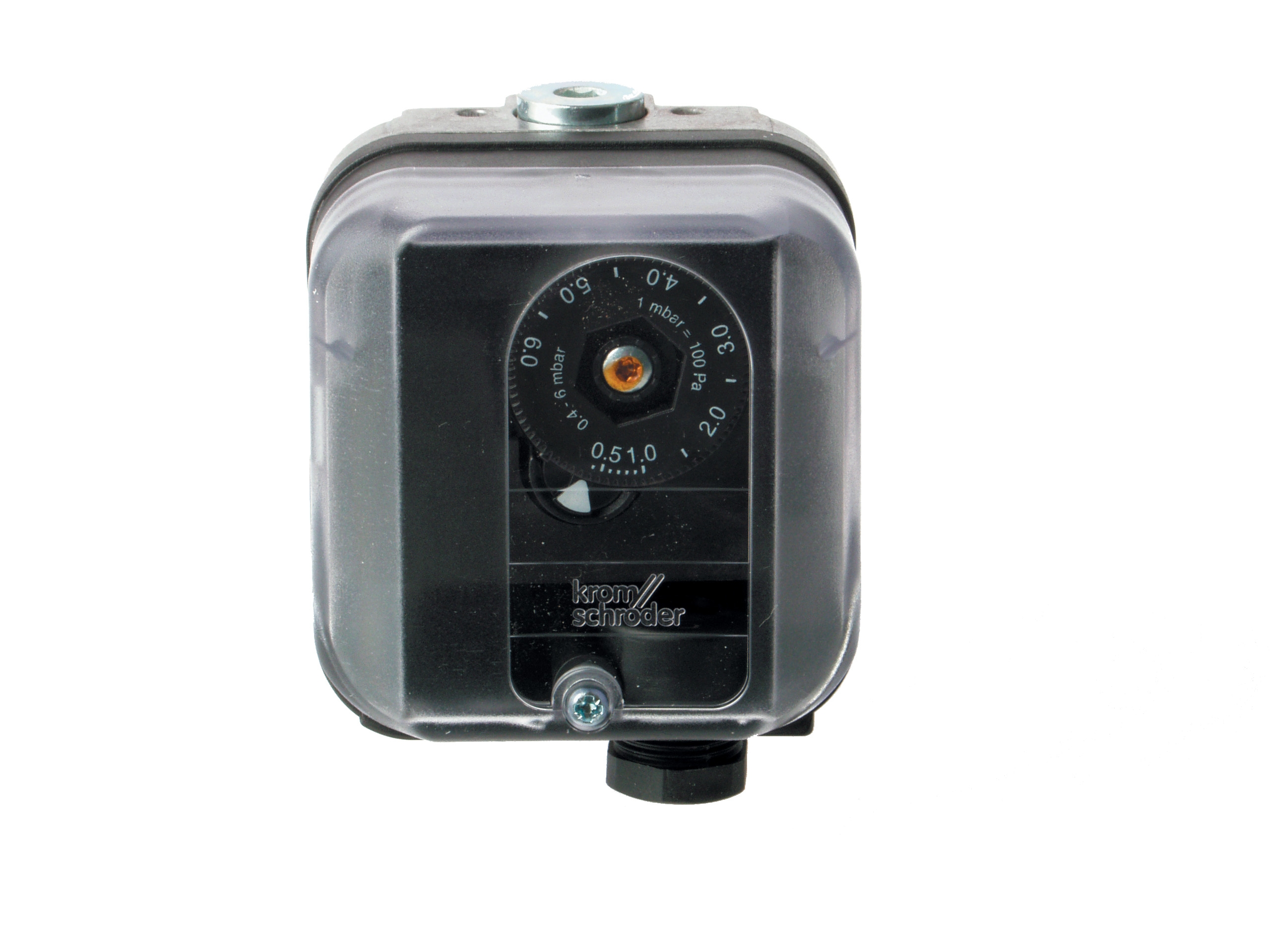
The Kromschroder Pressure Switch DG 50U/6 exemplifies modern burner control design with SIL 3 certification and EN 1854 compliance. This means the device meets rigorous international safety standards for dangerous substances. As a plant manager, understanding these ratings helps you evaluate equipment specifications during procurement.
Verification Procedure for Pressure Switches
1. Visual Inspection (Monthly)
- Check for corrosion on the switch body and terminals
- Verify cable connections are secure and not damaged
- Look for any signs of leakage around the pressure port
- Confirm the switch is mounted securely in its bracket
2. Pressure Response Testing (Quarterly)
- Isolate the burner safely and de-energize the control circuit
- Connect a calibrated pressure gauge to the switch port
- Gradually increase pressure while monitoring the electrical contacts with a multimeter
- Record the switch "make" pressure (activation point) and "break" pressure (deactivation point)
- These values should match the manufacturer's specification sheet within ±5%
- Document results in your maintenance log
3. Electrical Continuity Check (After Maintenance)
- With the switch isolated, verify continuity across the switch contacts at normal operating pressure
- Confirm the switch breaks continuity when pressure falls below minimum setpoint
- Use a multimeter set to resistance mode
- If readings are inconsistent, the switch requires calibration or replacement
Common Issues and Solutions
If your pressure switch fails testing, the most common causes are: (1) Internal contamination from dirty fuel or moisture, which prevents proper contact closure; (2) Setpoint drift from vibration or thermal cycling, which requires professional recalibration; (3) Electrical connector corrosion in humid Singapore conditions, which can be cleaned or replaced. Always reference the manufacturer's calibration certificate to confirm original setpoints before assuming drift has occurred.
Section 2: Flame Detection System Validation and Testing
The Role of Flame Detectors in Safety
Flame detectors provide continuous proof of combustion during burner operation. Modern industrial burners use either ultraviolet (UV) or infrared (IR) detection, with flame relay systems providing the safety logic. The Siemens Cell QRB4A-B036B40B is a proven two-wire flame detector designed specifically for oil burner applications, offering reliable detection across variable flame conditions.
If your flame detector fails, the burner control system should immediately shut down fuel supply and trigger an alarm. This is a critical safety function that requires regular validation.
Step-by-Step Flame Detection Testing
1. Optical Path Verification (Monthly)
- Inspect the flame detection lens for dust, soot, or water droplets
- Use a soft, dry cloth to gently clean the lens surface
- Never use harsh chemicals or abrasive materials
- Verify the detector has an unobstructed view of the flame
- Check that any protective covers or guards are not blocking the optical path
2. Functional Flame-Out Test (Quarterly)
- This test verifies the system shuts down when flame is lost
- Start your burner under normal operating conditions
- Carefully block the flame detector lens with a non-flammable material (metal plate or heavy cloth)
- The burner control should detect "loss of flame" within 4 seconds
- The fuel supply should shut off immediately
- Document the response time
- Remove the blocking material and verify the burner can be restarted normally
- If the burner does not shut down, do not attempt further operation—contact your service provider
3. Electrical Signal Strength Testing (Semi-Annually)
- This requires access to the control circuit and a suitable measurement tool
- Most flame detectors produce a small electrical signal (typically 0.5–3 mV) in the presence of flame
- Your control panel should have test points or a service connector for signal measurement
- With the burner running safely, measure the flame signal at the control input
- A weak signal (below 50% of baseline) may indicate detector aging or optical path contamination
- If signal strength is consistently low despite cleaning, the detector may need replacement
4. Response Time Validation (Annual)
- Engage a qualified testing service to measure the detector's actual response time to flame loss
- This typically involves specialized equipment and trained personnel
- Response time should not exceed the manufacturer's specification (typically 2–4 seconds)
- Results should be documented in your safety file
Section 3: Burner Control System Interlock Testing
Understanding Interlocks in Your Burner System
Interlocks are the logical connections between safety components that prevent unsafe burner startup. Before fuel can be introduced into the combustion chamber, the system must verify: (1) Air supply is adequate, (2) Temperature is within safe limits, (3) Pressure conditions are correct, (4) No fault conditions exist from previous shutdown cycles. These interlocks work together to create a safe operating envelope.
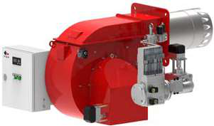
When you upgrade to high-capacity burners like the FBR HI-GAS P1500/M CE TL or the FBR HI-GAS P650/M CE TL, interlock testing becomes even more critical because the larger fuel volumes and energy release magnify the consequences of a control failure.
Systematic Interlock Verification Process
1. Pre-Start Safety Sequence Test (After Any Control Modification)
- Ensure the burner is shut down and the fuel supply is isolated
- Attempt to start the burner while introducing deliberate fault conditions:
* Block the air intake slightly (simulating low air pressure)
* Disconnect the flame detector connector (simulating detection failure)
* Manually prevent the pressure switch from activating (simulating low fuel pressure)
- In each scenario, the burner should fail to start and the control panel should display an appropriate fault code
- If the burner starts despite any simulated fault, the interlock logic is broken and requires immediate service
2. Shutdown Interlock Validation (Quarterly)
- Start the burner under normal conditions
- While running, introduce the fault conditions listed above, one at a time
- The burner should shut down within 2–4 seconds of detecting any fault
- Fuel supply should be completely cut off
- Record the shutdown time for each fault condition
- Restart the burner and verify normal operation is restored
3. Lockout Time Testing (Semi-Annually)
- After a fault shutdown, most control systems implement a "lockout" period (typically 30–60 seconds) before restart is allowed
- This prevents rapid cycling that could damage the burner or waste fuel
- Introduce a fault condition, allow the burner to shut down, then attempt immediate restart
- The system should prevent startup until the lockout period expires
- Verify the lockout timer is working correctly by observing the control panel
4. Dual-Fuel System Interlocks (If Applicable)
- Plants using the FBR KN 350/M dual-fuel burner should test fuel-switching interlocks
- The system must verify one fuel is completely shut off before switching to the other
- Manually command a fuel switch and verify the "off" fuel solenoid closes before the "on" fuel solenoid opens
- This prevents dangerous mixing of fuels in the combustion chamber
- Document switch times and fuel crossover intervals
Section 4: Documentation, Compliance, and Best Practices
Building Your Safety Verification Record
Regulatory compliance in Singapore requires documented evidence of safety system testing. Your plant needs a centralized record system that captures:
- Equipment identification: Burner model, serial number, fuel type, capacity
- Test dates and results: Pressure readings, response times, fault conditions tested
- Pass/fail status: Clear indication of whether each component met specifications
- Corrective actions: Any maintenance, calibration, or replacement performed as a result of testing
- Technician signature: Name and credentials of the person who performed the test
- Follow-up schedule: Next testing date and any interim monitoring requirements
This record becomes your evidence of due diligence and is essential if a safety incident occurs. 3G Electric recommends storing these records digitally with secure backup, as well as maintaining printed copies for your safety file.
Creating a Sustainable Testing Schedule
Different components require different testing frequencies:
- Monthly: Visual inspection of all combustion components, lens cleaning, connector checks
- Quarterly: Pressure switch setpoint verification, functional flame-out testing, interlock basic checks
- Semi-annually: Electrical signal strength measurement, lockout timer validation, dual-fuel switching tests
- Annually: Complete pressure switch calibration, flame detector response time measurement by qualified service provider, comprehensive interlock sequence testing
For plants operating continuously (24/7 operations common in Singapore), conduct half of your quarterly tests in the first month and half in the third month to avoid bunching maintenance activities.
Training Your Team
Many testing procedures can be performed by trained plant staff without specialized technicians, reducing costs and improving response time. Invest in:
- Basic electrical safety certification for staff handling control circuits
- Burner system training specific to your equipment models
- Practical hands-on sessions with your service provider
- Annual refresher training to maintain competency
Well-trained staff also notice early warning signs—unusual flame color, longer ignition times, or intermittent fault codes—that allow you to schedule maintenance before failures occur.
Troubleshooting Failed Verification Tests
When a component fails testing, systematic diagnosis prevents unnecessary replacement:
1. For pressure switch failures: First, verify your test gauge is calibrated and your testing procedure is correct. Many false failures result from operator error. If confirmed, clean the switch port and re-test. If still failing, send to the manufacturer for calibration or order a replacement.
2. For flame detector failures: Thoroughly clean the optical lens and verify the detector has a clear flame view. Environmental contamination in industrial settings is a common cause. Re-test after cleaning. If the signal remains weak or the response time is slow, the detector is aging and should be replaced as preventive maintenance.
3. For interlock failures: Review the control logic diagram in your burner manual to ensure you understand the intended sequence. Test each component individually first, then test the logic connections. A single failed pressure switch or detector often causes the entire interlock to fail, so isolate the component and test it separately.
Conclusion
Burners & Combustion safety verification is not a compliance checkbox—it is the foundation of safe plant operations. By implementing systematic testing of pressure switches, flame detectors, and interlocks, you detect problems before they become accidents. Over 35 years, 3G Electric has supplied industrial facilities with the reliable components and expert guidance needed to build safe combustion systems. Your commitment to thorough verification demonstrates to regulators, insurers, and your workforce that safety is a priority.
Start with a single test procedure this month—perhaps the pressure switch verification—and expand your program systematically. Document everything, train your team, and establish a sustainable testing schedule. These actions transform safety from a theoretical requirement into a practical, measurable part of your plant culture.