Burners & Combustion Control Systems: Selecting Relays and Safety Devices
Burners & Combustion systems in industrial heating applications depend heavily on reliable control electronics and safety instrumentation. For HVAC contractors in Southeast Asia operating in humid, corrosive, and high-temperature environments, selecting the correct burner control relay and pressure switch directly impacts system uptime, fuel efficiency, and regulatory compliance. With over 35 years of distribution experience, 3G Electric understands the critical role these components play in modern combustion systems.
When specifying a new burner system or retrofitting existing equipment, contractors must match control devices to the fuel type, ignition mode, power rating, and local safety standards. A mismatch between burner ignition characteristics and relay capabilities can lead to failed flame detection, unsafe shutdown cycles, or nuisance lockouts that interrupt production.
Understanding Burner Control Relay Requirements and Operating Modes
A burner control relay (also called a safety control unit) is the "brain" of a combustion system. It manages ignition sequences, monitors flame presence, controls air dampers, and triggers safe shutdown if combustion fails. The choice of relay depends on three primary factors: fuel type, ignition mode, and the presence of modulating controls.
Fuel Type Considerations
Gas burners, oil burners, and dual-fuel systems have different combustion characteristics and require different control logic. Gas burners typically ignite faster and develop flame more quickly, while oil burners require longer ignition delay times and more robust flame monitoring. The Kromschroder Relay BCU 570WC1F1U0K1-E is engineered for gas and mixed fuel applications with support for both direct ignition and intermittent or continuous pilot modes. This flexibility allows contractors to deploy a single relay across multiple burner configurations without redesigning the control cabinet.
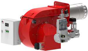
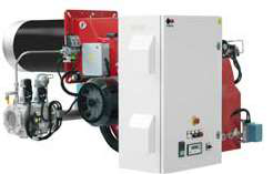
For dual-fuel or heavy oil applications requiring higher thermal power (1700–11,500 Mcal/h), equipment like the FBR KN 1300/M TL EL demands a control system capable of managing two-stage modulating operation. This requires a relay with proportional damper control and robust flame sensing at high combustion pressures.
Ignition and Flame Detection Modes
Ignition mode selection influences both safety and operational efficiency. Continuous pilot systems maintain a small flame between burner cycles, reducing ignition delay but increasing steady-state fuel consumption. Intermittent ignition systems light the main burner only when heat is demanded, improving efficiency at part-load but requiring faster flame development and more sensitive flame detection.
The Siemens Relay LFL 1.622 incorporates both ultraviolet (UV) and ionization flame monitoring, allowing contractors to select the detection method best suited to the fuel and burner design. UV detection responds quickly to visible flame and works well with gas burners, while ionization sensing detects flame through electrical conductivity and is preferred for oil applications. Dual-sensing capability provides redundancy and allows field adaptation if initial commissioning reveals suboptimal performance.
Pressure Switches: Sizing and Integration in Combustion Control Chains
Pressure switches in burner control systems serve multiple critical functions: confirming fuel supply pressure, detecting combustion pressure (proof of ignition), and protecting equipment from overpressure. Selecting an undersized switch can result in nuisance trips; oversizing reduces sensitivity and may delay fault detection.
Pressure Switch Classification and SIL Ratings
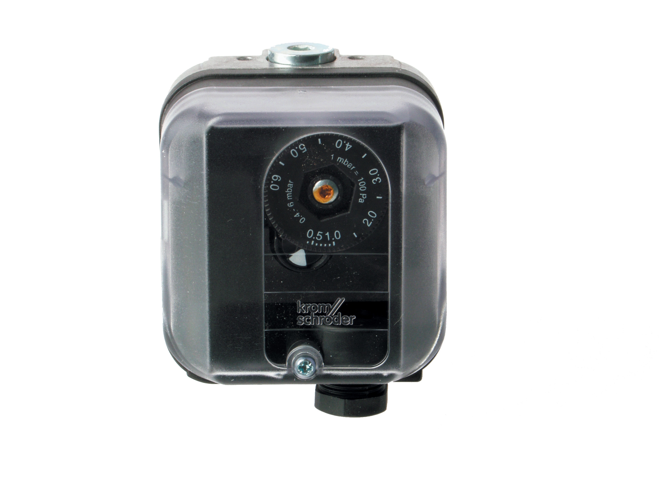
Industrial burner applications increasingly demand Safety Integrity Level (SIL) 3 certification, particularly in Southeast Asia where regulations follow EN and ISO standards. The Kromschroder Pressure Switch DG 50U/6 meets SIL 3 and Performance Level (PLe) requirements, with certifications spanning EN 1854, FM, UL, AGA, and GOST-TR. This multi-standard approval simplifies procurement for contractors operating across the region's diverse regulatory landscape.
When specifying a pressure switch, contractors must define:
- Operating pressure range: Fuel supply, combustion chamber pressure, and any secondary circuits
- Switch type: Single-pole or dual-pole contacts for series/parallel redundancy
- Hysteresis: Pressure differential between setpoint and reset; critical for avoiding oscillation during modulation
- Response time: How quickly the switch must detect pressure loss during a burner fault
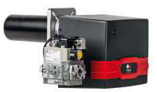
For a two-stage gas burner like the FBR GAS XP 60/2 CE TC EVO (116–630 kW), a single pressure switch with adjustable setpoint typically monitors fuel supply. For higher-power dual-fuel systems, contractors often install dual switches: one for fuel pressure proof and a second for combustion chamber pressure to detect flame loss.
Integration with Control Relays
The pressure switch connects to the control relay via hardwired contacts (typically monitored through safety relay modules). During the ignition sequence, the relay energizes an ignition transformer or spark electrode and waits for the pressure switch to confirm combustion pressure. If pressure does not rise within the expected time window (typically 2–5 seconds for gas, longer for oil), the relay enters a lockout state and demands manual reset.
In humid tropical environments common to Southeast Asia, electrical contacts can corrode or oxidize, causing intermittent faults. Specifying switches with gold-plated contacts and sealed enclosures (IP 65 or higher) minimizes field failures. The Kromschroder DG 50U/6's robust construction and multiple certification credentials make it a reliable choice for such demanding conditions.
Practical Commissioning and Troubleshooting of Relay and Pressure Switch Systems
Proper commissioning of burner control systems ensures reliable operation and establishes a baseline for future diagnostics. Contractors must verify relay function, pressure switch setpoints, and the complete fault logic before handing over equipment to the client.
Commissioning Checklist
1. Verify power supply and wiring: Confirm 24 VDC or 110/230 VAC availability and correct polarity. Ensure all safety interlocks (door switches, limit switches) are properly wired in series with the burner enable input.
2. Test ignition sequence: Manually initiate a burner start cycle and observe each phase—blower ramp, ignition spark or pilot light, main fuel valve opening, and flame detection. The relay should transition through each state without hanging or retreating.
3. Calibrate pressure switches: Using a portable pressure tester or the system's own pressure gauge, slowly increase pressure while observing the switch contact closure. Record the actual setpoint pressure (may differ from nominal) and reset point. For a pressure switch with 0.5 bar hysteresis set at 2.0 bar, the switch should close at 2.0 bar and remain closed until pressure drops below 1.5 bar.
4. Perform flame-out test: With the burner running, shut off fuel supply and confirm that the relay detects flame loss within its safety margin (typically 5 seconds). The relay should trigger a safe shutdown sequence—closing fuel valves and allowing the blower to purge.
5. Log all settings: Record setpoints, response times, and any field adjustments. This becomes critical reference data for warranty support and future troubleshooting.
Common Field Issues and Diagnostics
Nuisance lockouts often stem from pressure switch oscillation near the setpoint. During modulation, fuel pressure may fluctuate slightly, causing the pressure switch to cycle rapidly and confuse the relay's flame detection logic. Solution: increase the setpoint 0.2–0.3 bar above the minimum operating pressure, or specify a switch with larger hysteresis.
Delayed flame detection usually indicates either a slow relay response time, insufficient flame intensity for the detector type, or a problem with the burner itself (poor air-fuel mixing, weak ignition). Verify that the burner's thermal power and fuel type match the relay's design (UV relays are less effective with weak oil flame, for example). If the burner is correct, the relay may be faulty and require replacement.
In tropical climates, condensation inside relay or pressure switch enclosures can cause corrosion of internal contacts and circuit boards. Specify IP 65+ sealed units and use desiccant plugs or silica gel sachets in control cabinets. Inspect and replace these sachets annually.
Selecting Components for Southeast Asian Operating Conditions
Southeast Asia's hot, humid climate with seasonal monsoon rains presents unique challenges for burner control systems. Salt spray near coastal areas accelerates corrosion. Dust and high ambient temperatures stress electronic components. Power supply instability (brownouts and surges) can damage control electronics.
When specifying burner control systems for this region, prioritize:
- Sealed enclosures: IP 65 minimum for field-mounted switches and junction boxes; IP 54 for indoor control cabinets with active cooling.
- Stainless steel or nickel-plated hardware: Avoid mild steel fasteners that rust rapidly in humidity.
- Surge protection: Install varistors or dedicated surge suppressors on all 24 VDC outputs and solenoid coils to protect relay electronics from voltage spikes.
- Thermal management: Ensure adequate ventilation in control cabinets; use thermostatic fans if ambient temperature exceeds 35 °C.
- Local service availability: Select components from suppliers (like 3G Electric) with established distribution networks and local technical support, ensuring spare parts and expert guidance are accessible when field issues arise.
The Kromschroder BCU 570WC1F1U0K1-E and Siemens LFL 1.622 are both proven in Southeast Asian industrial environments and widely stocked by 3G Electric, reducing lead times and supporting faster troubleshooting when issues occur.
Conclusion
Burners & Combustion control systems are only as reliable as their weakest component. By carefully matching control relays and pressure switches to the application's fuel type, power rating, ignition mode, and environmental conditions, HVAC contractors can design systems that operate safely and efficiently for 15+ years in demanding Southeast Asian conditions. 3G Electric's 35+ years of industry experience and deep product knowledge make us a trusted partner for specifying these critical components. Contact our technical team to discuss your next burner control project.