Understanding Burners & Combustion Control Architecture
Burners & Combustion systems in modern industrial plants are not standalone heat sources—they are complex integrated systems where control logic, safety monitoring, and fuel regulation work in concert. For plant managers responsible for operational reliability, understanding how these components interact is essential to preventing costly downtime and safety incidents.
A typical burner control system consists of three functional layers: the burner itself (which provides thermal energy), the control relay (which orchestrates ignition and flame monitoring), and the interlocking devices (pressure switches, air proving switches, and flame detectors) that enforce safety sequences. When any component fails to communicate correctly with the others, the entire system can become unreliable or unsafe.
With over 35 years of experience distributing industrial equipment across Southeast Asia, 3G Electric has observed that plant managers often overlook control system integration during equipment procurement. Many focus solely on burner power ratings while treating safety relays and interlocks as afterthought components. This approach frequently results in commissioning delays, nuisance shutdowns, and regulatory compliance gaps.
The key to effective burner management is viewing the control system as a unified specification rather than separate items. Your choice of safety relay determines which ignition modes, flame detection methods, and interlock configurations are available to you. The pressure switches you select must be compatible with that relay and certified to the same safety standards. This article provides practical guidance on making these integrated decisions.
Selecting the Right Burner Control Relay for Your Plant Conditions
The control relay is the "brain" of your burner system. It receives signals from sensors, executes the ignition sequence, monitors flame presence, and commands shutdown if safety conditions are violated. Choosing the correct relay type directly impacts your ability to operate efficiently and safely.
Primary Relay Selection Criteria for Plant Managers:
First, identify your fuel type and ignition strategy. Gas-only burners can use simpler control logic than dual-fuel systems, which must manage transitions between fuels without unsafe fuel accumulation. If your plant operates continuous process heating (such as thermal oil systems or drying chambers), you need a relay supporting continuous pilot ignition. If you run batch operations with frequent on-off cycles, intermittent pilot ignition is more fuel-efficient.
Second, determine your required safety integrity level (SIL) based on local Singapore regulations and your facility's risk assessment. Most industrial heating applications in Singapore fall into SIL 2 or SIL 3 categories. A SIL 3-rated relay provides higher confidence in safety function performance, particularly important if your burner heats pressurized vessels or serves critical process operations.
Third, evaluate flame detection method compatibility. Ultraviolet (UV) flame detection is faster and more immune to false signals from ambient light, making it suitable for outdoor installations or facilities with bright work environments. Ionization detection is cost-effective for indoor applications with stable ambient conditions. Some plant managers choose dual-detection capability for maximum reliability—the relay simply uses whichever signal is available.
For example, the Kromschroder Relay BCU 570WC1F1U0K1-E supports both direct ignition and intermittent/continuous pilot modes, complies with EN 746-2 and EN 676 standards, and accommodates multiple ignition strategies. This flexibility means you can configure the relay to match your specific operational needs—whether you're running a small modulating burner or a high-capacity system with redundant safety requirements.
When specifying a new burner control system or replacing an aging relay, document your current operational practices. Do you use the pilot flame year-round or seasonally shut down? Do your process loads vary significantly, requiring modulating burner capacity? Do you operate in high-vibration or high-temperature environments that might degrade sensor electronics? These real-world conditions determine which relay features justify their cost.
Designing Interlock Systems: Pressure Switches and Safety Sequencing
Interlocks are the safety gatekeepers of your burner system. They enforce mandatory conditions before ignition is permitted and shutdown sequences if operating parameters drift outside safe limits. Pressure switches are the most common interlock devices in industrial burner applications, monitoring fuel supply pressure, air proving pressure, and combustion chamber pressure.
Critical Interlock Logic for Plant Operations:
Fuel pressure monitoring prevents ignition if fuel supply is inadequate, avoiding weak flames and incomplete combustion. Most regulations require fuel pressure to be verified before the ignition sequence starts. If pressure falls during operation, the burner must shut down safely. The pressure switch must open and close decisively—vague analog readings are insufficient.
Air proving interlocks confirm that combustion air supply meets minimum requirements before ignition. For forced-draft burners, this typically involves verifying air fan operation and air duct pressure. Without this interlock, you risk igniting fuel in a non-combustible atmosphere, creating dangerous fuel accumulation.
Combustion chamber pressure monitoring (or "furnace pressure control") maintains slight negative pressure in the combustion chamber, preventing hot gases from escaping into the boiler room. This protects personnel and equipment while optimizing burner efficiency.
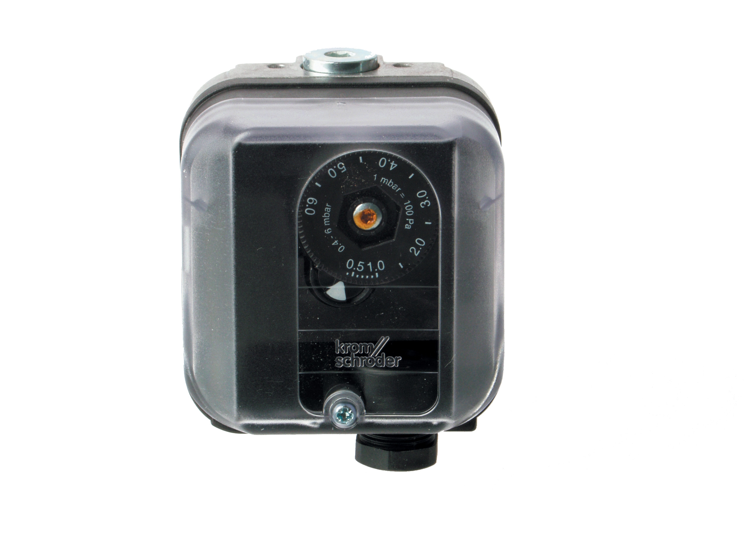
The Kromschroder Pressure switch DG 50U/6 is specifically engineered for burner control applications and is rated SIL 3 with Performance Level e. It meets EN 1854, FM, UL, AGA, and GOST-TR certifications—a comprehensive compliance profile important for Singapore facilities operating under multiple regulatory frameworks. The multiple certifications mean this device can be integrated into systems serving different regional customers or meeting various insurance and equipment standards.
Practical Interlock Configuration Considerations:
When designing your interlock logic, consider both safety and operational reliability. Over-restrictive interlocks can cause nuisance shutdowns that interrupt production and erode operator confidence in the safety system. Under-restrictive interlocks may allow unsafe conditions to persist.
For example, if your fuel pressure switch is set too high, normal fuel supply variations will trigger unnecessary burner shutdowns. If set too low, you may ignite with marginal fuel supply, producing incomplete combustion and energy waste. Work with your burner supplier to establish pressure setpoints based on your specific fuel system design, not generic industry defaults.
Document all interlock setpoints and test frequencies in your plant's standard operating procedures. Pressure switches require annual calibration and functional testing to ensure they respond correctly. Many plants in Singapore have experienced compliance failures during regulatory audits because interlock testing was not formally documented.
Consider installing isolation ball valves at each pressure switch connection point. This allows you to remove and test or replace switches without depressurizing your entire fuel system, reducing downtime during maintenance.
Integrating Control Relays with Flame Detection and Multi-Fuel Operations
As your plant scales or production demands shift, you may transition from single-fuel to multi-fuel burner systems. Integration complexity increases significantly, and control system selection becomes more critical.
Flame Detection in Integrated Systems:
The Siemens Relay LFL 1.622 is a safety control unit specifically designed for gas, oil, or dual-fuel burners with medium to high power ratings. It features both UV and ionization flame monitoring, allowing operators to verify flame presence through two independent sensing methods. For plant managers operating in tropical Southeast Asia where humidity and ambient light conditions vary, dual-detection capability provides redundancy that reduces false alarms.
The controlled air damper capability integrated into this relay type enables modulating burner operation—gradually opening or closing the air damper to match fuel flow rate, optimizing combustion efficiency across varying load conditions. This feature alone can reduce fuel consumption by 8–12% in facilities with variable thermal loads.
Dual-Fuel and Heavy Oil Burner Considerations:
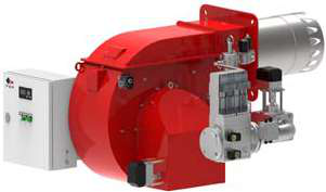
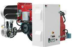
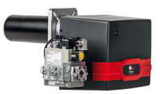
If your plant operates heavy oil burners or dual-fuel systems, control complexity increases because each fuel type has different ignition characteristics, viscosity requirements, and combustion parameters. The FBR GAS XP 60/2 CE TC EVO is a two-stage modulating gas burner delivering 116–630 kW, while the FBR KN 1300/M TL EL is a dual-fuel heavy oil burner operating from 1700 to 11500 Mcal/h with modulating control.
When operating dual-fuel systems, your control relay must manage fuel changeover logic automatically. During a fuel switch, there is a transition window where one fuel is shutting down while the other is ramping up. If the transition is not managed correctly, you risk simultaneous operation of both fuels (creating over-firing conditions) or a period with no fuel ignition (losing flame).
Plant managers should establish clear fuel switching protocols: under what conditions does the system switch fuels? Are there minimum plant load thresholds? During heating season transitions, do you switch based on fuel cost, fuel availability, or environmental conditions? Document these decisions and communicate them to operators and maintenance staff.
Integration Testing and Commissioning:
When integrating a new control relay with existing or new burner equipment, rigorous testing is non-negotiable. Work with your equipment supplier to conduct full functional testing of the ignition sequence, flame detection response, and interlock shutdown scenarios. Test each potential failure condition: fuel pressure loss, air proving failure, flame detection failure, and manual shutdown command.
For plant managers in Singapore with existing installations, this integration exercise should be repeated whenever you upgrade control equipment. Older relay designs may not communicate correctly with newer pressure switches or flame detectors, creating intermittent safety failures that are difficult to diagnose.
Operational Best Practices for Burner Control System Management
Control system reliability requires continuous monitoring and maintenance discipline.
Daily Operator Responsibilities:
Train operators to recognize normal versus abnormal burner startup sequences. A properly functioning system should ignite cleanly within 2–3 seconds of the ignition command, with no hesitation or multiple re-light attempts. Slow startups or repeated ignition attempts indicate control system sluggishness and warrant immediate inspection.
Instructs operators to log any interlock-triggered shutdowns, even brief ones. Nuisance shutdowns are often precursors to component failure. Pressure switch setpoints may be drifting, or fuel supply may be becoming marginal. Early detection prevents unplanned outages.
Maintenance Schedule for Control Components:
Pressure switches require annual functional testing and calibration by qualified technicians. UV flame detectors require periodic cleaning because dust accumulation reduces signal strength. Ionization electrodes may require cleaning or replacement every 2–3 years depending on fuel quality and combustion cleanliness.
Relay electronics are generally robust, but environmental factors matter. If your burner operates in high-vibration areas (such as facilities with rotating machinery nearby), mounting quality becomes critical. Use vibration-dampening relay enclosures and flexible conduit connections to reduce mechanical stress on circuit boards.
Seasonal Commissioning:
If your plant operates seasonally or with extended idle periods, establish a commissioning protocol before each startup season. Test fuel supply pressure, verify air proving function, confirm flame detection sensitivity, and execute a complete burner shutdown sequence. Many safety-related failures occur during the first few days of the heating season after prolonged shutdown.
Documentation and Regulatory Compliance:
Maintain detailed records of all control system maintenance, testing, and any modifications. Singapore's regulatory framework increasingly requires documented proof that safety-related equipment is maintained to manufacturer specifications. Create a control system asset register listing each relay, pressure switch, and flame detector with installation date, manufacturer, and certification numbers. This documentation supports regulatory audits and provides continuity when maintenance staff change.
With 35+ years of experience supporting industrial operations across Southeast Asia, 3G Electric has observed that plants with the most reliable burner systems treat control specification and integration as carefully as they specify the burners themselves. The modest investment in proper control system design and documentation pays dividends through reduced downtime, improved fuel efficiency, and confident regulatory compliance.