Understanding Common Pumps & Compressors Failure Modes
After three decades distributing industrial equipment across Southeast Asia, 3G Electric has observed that most Pumps & Compressors failures fall into predictable patterns. Rather than random breakdowns, failures typically signal underlying system issues—misalignment, cavitation, pressure spikes, or fluid degradation. Your maintenance team's ability to recognize these patterns directly impacts downtime and repair costs.
The most common failure modes include:
- Cavitation (sudden pressure drops, pulsating discharge, noise)
- Seal leakage (external fluid weeping, internal slippage)
- Bearing wear (increased vibration, temperature rise, audible grinding)
- Pressure relief valve malfunction (inability to reach setpoint, bypass leakage)
- Motor coupling misalignment (accelerated bearing wear, unusual vibration signature)
- Fluid contamination (varnish buildup, accelerated wear, reduced efficiency)
When a pump or compressor underperforms, maintenance teams often replace components without understanding the root cause—leading to repeated failures. A structured diagnostic approach prevents this costly cycle.
Systematic Diagnostic Protocol for Failing Pumps & Compressors
Step 1: Establish Performance Baseline
Before assuming failure, confirm actual vs. expected performance. Record:
- Flow rate: Measure discharge volume per minute (L/min). Compare to nameplate specifications.
- Pressure: Note both system pressure and relief valve setpoint. Use calibrated gauges—many team errors stem from faulty pressure instruments.
- Temperature: Monitor outlet fluid temperature. Excessive heat (>65°C) indicates slippage or excessive restriction.
- Electrical input: For motor-driven units, verify amperage against nameplate FLA (Full Load Amperage). Under-load motors suggest cavitation or discharge blockage; over-load motors indicate mechanical resistance or system backpressure issues.
- Vibration signature: Use simple hand-feel assessment or portable vibration meter. Quantify baseline values for trend tracking.
Step 2: Interview the Operator
Your maintenance technician should ask:
- When did performance degrade (sudden or gradual)?
- What changed in the system (feedstock, flow demand, external temperature)?
- Are there unusual sounds (cavitation chirp, bearing growl, relief chatter)?
- Has the unit been serviced recently or left idle for extended periods?
Many "failures" are actually operator misuse or system configuration errors.
Step 3: Physical Inspection
External assessment:
- Check fluid level in reservoir (low levels cause cavitation)
- Inspect suction strainer for blockage or contamination
- Look for external leakage around seals, gaskets, and connections
- Verify inlet line diameter and length (oversized suction lines cause cavitation)
- Confirm coupling alignment by using a straightedge or laser alignment tool
- Scan motor windings and bearing housings with an infrared thermometer
- Localized hot spots indicate friction or electrical resistance
- Uniform temperature rise suggests normal load operation
- High-pitched chirping = cavitation (suction-side pressure drop)
- Low-frequency growl = bearing wear (radial play)
- Rapid clicking = valve spooling issues or relief chatter
Step 4: Fluid Analysis
Fluid condition is the most overlooked diagnostic factor. Send samples to a lab for:
- Viscosity index: Confirms fluid temperature stability
- Acid number (TAN): Detects oxidation and fluid degradation
- Particle count (ISO 4406): Identifies contamination sources
- Water content: Even 2-3% water causes seal and bearing damage
- Ferrous content: Measures internal wear rate
Degraded fluid doesn't just reduce efficiency—it accelerates component wear and masks the original failure cause.
Practical Repair Strategies for High-Impact Failures
Addressing Cavitation (Pressure Drop at Suction)
Diagnosis: Discharge pressure cannot reach target; audible chirping; intermittent flow.
Root causes:
- Suction strainer clogged (most common in Singapore's humid climate—mold and corrosion thrive in mineral oil)
- Suction line diameter too small (velocity >1.2 m/s causes drop)
- Inlet check valve stuck or leaking
- Reservoir fluid level below pump intake
- Fluid viscosity too high for intake temperature
1. Stop unit immediately—cavitation destroys pump internals within hours
2. Clean or replace suction strainer
3. If strainer was clean, measure suction line velocity: Flow (L/min) ÷ 60 ÷ line area (cm²) = velocity (m/s)
4. Verify inlet check valve operation by hand-test pressure
5. Check fluid viscosity at actual operating temperature—if viscosity is >500 cSt at intake temperature, consider a lower-viscosity fluid suitable for your climate
Prevention: Service suction strainer every 500 operating hours; maintain oil level 75-100% of reservoir capacity; verify suction line diameter during system design phase.
Seal Leakage and Slippage
Diagnosis: Fluid weeping at shaft seal; gradual pressure loss over minutes; reduced flow despite normal motor load.
Root causes:
- Shaft seal worn (typical life: 5,000-10,000 hours depending on pressure and cleanliness)
- Seal faces damaged during assembly or by contaminated fluid
- Excessive radial or axial runout from bearing wear
- Pressure pulsation from relief valve chatter or cavitation (flexes seal faces)
1. If external leakage only, depressurize and inspect seal contact surfaces under magnification
2. Measure shaft runout with a dial indicator; radial runout >0.1 mm indicates bearing damage
3. If slippage (flow loss) without external leak, internal seal has failed—requires disassembly
4. Replace seals only after confirming pressure system is stable (relief valve functional, no cavitation)
5. Use OEM seal kits to ensure proper material compatibility with your working fluid
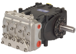
For units like the Pratissoli PUMP SN7061 L, which operates at 150 bar, seal failure accelerates if system pressure spikes above rated working pressure. Install a calibrated pressure gauge immediately upstream of the pump to track pressure trends.
Prevention: Maintain system cleanliness (ISO 4406 code ≤18/16/13); perform relief valve calibration checks every 12 months; log pressure and temperature trends monthly to catch pressure spikes early.
Motor Coupling Misalignment
Diagnosis: Rapid bearing wear (short life after replacement); excessive vibration at coupling; uneven load distribution.
Root causes:
- Thermal growth: Motor and pump expand differently; couplings designed for cold state become misaligned when hot
- Foundation settling: Concrete shifts; mounting bolts loosen (Singapore's humidity and temperature swings accelerate this)
- Flexible coupling elastomer degraded: Rubber hardens or tears, losing damping ability
1. Use a laser alignment tool (far more accurate than straightedge method)
2. Perform alignment checks when system is at thermal steady-state (typically 2-4 hours of operation)
3. Measure both angular and parallel misalignment; target <0.05 mm parallel, <0.5° angular
4. Inspect coupling elastomer: Cracking, hardening, or discoloration indicates replacement needed
5. Check foundation bolts with calibrated torque wrench; retorque if loose
For high-power units like the Pratissoli SN7061 L (18.4 kW at 1450 rpm), misalignment creates radial loads on bearings that accelerate failure by 50-70%.
Prevention: Perform laser alignment during initial commissioning and every 2 years thereafter; inspect coupling elastomer visually during quarterly rounds; log vibration amplitudes to detect gradual misalignment growth.
Relief Valve Malfunction
Diagnosis: Pressure overshoots setpoint; relief valve "chatters" (audible rapid opening/closing); bypass flow at idle.
Root causes:
- Valve seat contaminated (silt, oxidized fluid, varnish deposits)
- Pilot pressure line restricted or blocked
- Spring fatigue or corrosion
- Spool stiction (friction preventing smooth movement)
1. Isolate valve and depressurize system
2. Visually inspect valve spool and seat under magnification (look for deposits or scratches)
3. Flush pilot pressure line with clean fluid; check pilot check valve operation
4. Test spring tension by comparing measured cracking pressure to nameplate setpoint
5. If setpoint drifts >2 bar from nominal, replace spring cartridge
6. Never file or polish valve seats on-site; send assembly to certified calibration center
Prevention: Change fluid every 4,000-6,000 operating hours (more frequently in humid environments like Singapore where moisture ingress accelerates oxidation); install pilot line filters; schedule relief valve calibration every 18 months.
Strategic Replacement and Upgrade Decisions
When to Repair vs. Replace
Maintenance teams face this decision frequently. Use this framework:
Repair if:
- Failure is localized (single seal, bearing, or valve)
- Unit age <60% of typical service life (pumps typically 10-15 years for centrifugal, 15-20 years for gear/vane)
- Repair cost <40% of replacement cost
- System specifications still match application demands
- Multiple component failures within 12 months (indicates systemic issue)
- Cavitation or misalignment has damaged impeller or rotor (internal damage typically requires full replacement)
- Unit age >70% of service life with performance degradation
- Replacement cost <3× annual repair cost (total cost of ownership calculation)
- Newer units offer 15%+ efficiency gain for your duty cycle
Upgrade Path for Efficiency Gains
If replacement is justified, consider upgrading to higher-efficiency alternatives. For example:
- Delta Pump VM3 RL 2.4 (SKU: DEL05131) offers integrated solenoid valve design, reducing system parasitic losses compared to separate valve configurations. For oil burner fuel applications requiring 20 ±0.3 bar setpoint, this integrated approach eliminates pressure spikes from valve delay.
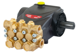
- Interpump PUMP W916 R (SKU: W0091600U-100) delivers 18 L/min at 160 bar with 5.51 kW input—typical for high-pressure wash systems. Compare this to older 4-liter-per-minute units: the modern pump cuts energy consumption per unit output by 20-30%.
- Interpump PUMP E2B2014 L (SKU: E2B2014BS-000) is compact (7 kg) yet rated for 200 bar and 14 L/min. For retrofit projects with spatial constraints, this unit enables system modernization without mechanical redesign.
When specifying replacements, document:
- Original duty cycle (pressure, flow, hours/year, fluid type)
- Historical failure modes and maintenance costs (3-year average)
- Current system efficiency vs. modern alternatives
- Total cost of ownership over 10-year horizon
3G Electric's 35+ years distributing industrial equipment means we've tracked performance data across thousands of installations. This historical perspective helps your team avoid performance mismatches and select units proven in Singapore's tropical climate and 24/7 industrial duty cycles.
Building a Sustainable Maintenance Culture
Documentation and Trend Tracking
The most successful maintenance teams maintain detailed logs:
- Operating parameters: Pressure, flow, temperature, amperage (weekly)
- Service events: Seal replacements, fluid changes, relief valve calibration (date + technician)
- Failure analysis: Root cause assessments with supporting data (whenever replacement occurs)
- Vendor data: Equipment age, model, serial number, installation date, original performance baseline
This data reveals patterns invisible in single snapshots. A 2-bar pressure drift over six months is minor; a 2-bar drift in two weeks signals impending relief valve failure.
Technician Competency
Invest in your team's diagnostic skills:
- Fluid sampling and interpretation: Understanding particle count, viscosity, and contamination source transforms troubleshooting from guesswork to engineering
- Vibration and acoustic analysis: Learning to distinguish cavitation from bearing wear prevents misdiagnosis
- Thermal imaging: Identifying friction sources quickly narrows troubleshooting scope
- Pressure and flow measurement: Proper instrument selection and calibration prevents false diagnostic paths
Proper training pays dividends: technicians who understand root causes reduce repeat failures by 40-60% and mean time to repair (MTTR) by 30-50%.
Spare Parts Strategy
Stock these critical items based on your equipment mix:
- Seals and gasket kits (exact model-specific sets to avoid cross-contamination)
- Suction strainers and filter elements
- Relief valve cartridges and springs
- Flexible coupling elastomers and alignment shims
- Replacement pump/compressor units for your most critical systems (enables rapid swap during diagnosis)
Maintain fluid inventory appropriate to your system volume, anticipated change frequency, and climate conditions. In Singapore's tropical environment, fluid oxidation accelerates; track fluid age and condition through lab analysis rather than calendar intervals alone.