Understanding Cavitation in Pumps & Compressors
Cavitation occurs when the absolute pressure at the pump inlet falls below the fluid's vapor pressure, causing dissolved gases and vaporized liquid to form bubbles within the pump chamber. When these bubbles collapse near solid surfaces—typically at the impeller eye or within gear mesh zones—they release microsized jets at velocities exceeding 400 m/s, creating localized pressures of 1–2 GPa. This phenomenon causes material erosion, noise amplification, and progressive loss of volumetric efficiency.
For procurement engineers, cavitation is not a minor performance issue—it is a system-level problem that signals undersized inlet piping, inadequate suction lift, fluid contamination, or incorrect reservoir pressurization. Unlike wear that develops gradually, cavitation erosion can reduce pump displacement efficiency by 10–15% within weeks and lead to catastrophic seal or bearing failure within months. Across 3G Electric's 35+ years of industrial equipment distribution, we have documented that proper inlet condition management eliminates more than 90% of premature pump failures attributed to cavitation.
Net Positive Suction Head (NPSH): The Quantifiable Prevention Standard
The critical parameter governing cavitation risk is Net Positive Suction Head (NPSH), which is the absolute pressure head available at the pump inlet minus the fluid's vapor pressure head at operating temperature.
NPSH Available (NPSHA) is calculated as:
NPSHA = (Patm + Psource) / ρg - Pvapor / ρg - Hf_losses
Where:
- Patm = atmospheric pressure (101.3 kPa at sea level)
- Psource = pressure at the source fluid surface (typically 0 for gravity-fed reservoirs)
- ρg = fluid weight density
- Pvapor = fluid vapor pressure (ISO 46 hydraulic oil at 40°C ≈ 0.1 kPa; at 60°C ≈ 0.5 kPa)
- Hf_losses = head losses in inlet piping and filters
The safety rule: NPSHA must exceed NPSHR by a minimum margin of 0.5 m in normal operation and 0.3 m under transient conditions. Many plant failures occur at marginal NPSHA/NPSHR ratios of 1.0–1.2, where cavitation initiates silently before becoming audible.
Practical Calculation Example: Series 73 Installation
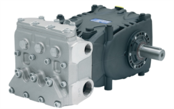
Consider a Pratissoli MW40 pump (211 L/min, 210 bar, 85 kW) in a Singapore marine manufacturing facility operating at 1500 rpm:
- Atmospheric pressure: 101.3 kPa
- Reservoir at sea level, 1.5 m above pump inlet center
- Inlet pipe: 50 mm ID, 3 m length with one 90° elbow, 25 μm filter
- ISO 46 hydraulic fluid at 50°C (vapor pressure ≈ 0.3 kPa)
- Fluid density: 860 kg/m³
Velocity in 50 mm pipe: V = Q / A = (211 L/min × 10⁻⁶) / (π × 0.025²) ≈ 0.57 m/s (acceptable; <1.5 m/s rule)
Head loss (Darcy–Weisbach + fitting): Hf ≈ 0.35 m
NPSHA = (101.3 + 0) / (860 × 9.81) − (0.3) / (860 × 9.81) − 0.35
NPSHA = 0.0120 − 0.00004 − 0.35 ≈ −0.338 m (negative!)Result: This configuration will cavitate. Remedy: raise reservoir 0.6 m higher, downsize inlet pipe to 38 mm (reduces loss to ~0.12 m), or add a 0.1–0.2 bar charge air pressure to the reservoir.
Inlet Condition Management: Design and Procurement Criteria
Preventing cavitation requires specifying inlet conditions as rigorously as you specify pump displacement and pressure rating.
Inlet Piping Velocity and Sizing
- Maximum inlet velocity: 1.5 m/s for hydraulic pumps; 1.2 m/s for systems prone to cavitation
- Minimum pipe ID: Solve V = 4Q / (π D²) for D, where Q is in m³/s
- For the MW40 example (211 L/min = 0.00352 m³/s): D_min = √(4 × 0.00352 / (π × 1.5)) ≈ 0.0547 m = 54.7 mm → specify 63 mm (2.5") or 76 mm (3") nominal
Suction Lift and Reservoir Design
- Gravity-fed systems: limit suction lift to 0.5 m maximum in tropical climates (higher fluid temperatures increase vapor pressure)
- Pressurized reservoir: maintain 0.1–0.3 bar air charge above fluid surface; prevents cavitation during transient demand spikes
- Reservoir height: position at least 1.5–2.0 m above pump inlet center for centrifugal booster pumps; position pump inlet submerged for compact installations
Inlet Filter Specification
Inlet filters are the most common cavitation trigger. Standard 25 μm absolute filters create 0.15–0.25 m of additional head loss:
- Solution 1: Use 100–150 μm inlet strainers (basket type, not spin-on) to keep losses <0.05 m
- Solution 2: Specify low-pressure-drop filters rated for 0.10 m maximum at design flow
- Solution 3: Implement clogging indicators; replace filters before nominal service life if head loss approaches 0.15 m
Fluid Property Control
Cavitation sensitivity increases dramatically with:
- Temperature rise: ISO 46 oil at 60°C has 5× higher vapor pressure than at 40°C. Maintain fluid temperature ≤55°C via cooler sizing
- Air content: entrained air reduces bulk modulus by 50% and lowers effective vapor pressure threshold. Maintain fluid degassing via reservoir baffles and settling time
- Contamination: particles >20 μm act as nucleation sites for bubble formation. Maintain ISO 4406 16/14/11 cleanliness minimum
System Design and Procurement Strategy for Cavitation-Free Operation
When specifying pump systems for Singapore's high-humidity, high-temperature industrial environment, your procurement specification should mandate:
1. Inlet Condition Schedule
For Pratissoli KF30 (106 L/min, 200 bar, 40 kW) installations:
- Inlet pipe diameter: 38 mm minimum
- Suction lift: 0.5 m maximum (gravity fed) or 0.1–0.2 bar pressurized
- Inlet filter: 100 μm basket, <0.05 m clean loss
- Reservoir volume: ≥2× pump displacement (≥212 L for KF30)
- Fluid cooler: sized for ≤55°C steady-state operation
- Vapor pressure margin: NPSHA – NPSHR ≥ 0.5 m at rated speed and 55°C fluid temperature
2. Compact Pump Selection for Space-Constrained Installations
Where traditional suction-lift arrangements are infeasible, 3G Electric supplies low-displacement gear pumps with favorable cavitation characteristics:
- Interpump E1D1808 L (8 L/min, 180 bar, 2.72 kW, 2800 rpm): compact footprint, minimal inlet sensitivity due to small displacement and high speed tolerance
- Interpump ET1C1612 SX*D20 (12 L/min, 160 bar, 3.68 kW, 1750 rpm): PTFE construction, excellent reliability in high-pressure circuits requiring minimal NPSH
- Pratissoli SS71153 (122 L/min, 160 bar, 37.5 kW, 800 rpm): low-speed design inherently reduces cavitation risk; suitable for direct-coupled or gearbox-driven applications
3. Transient Condition Monitoring
Cavitation often initiates during transient events (sudden load demand, fast solenoid valve closure, pressure spike). Procurement should specify:
- Pilot-operated check valves to prevent inlet vacuum during load release
- Accumulator sizing to limit pressure ramp rates to <50 bar/s
- Clogging indicator on inlet filters (audible or electrical signal) to prevent unplanned suction line starvation
Maintenance and Diagnostic Protocol
Early cavitation detection (before erosion):
- Audible high-pitched noise (1–2 kHz) emanating from pump inlet region
- Volumetric efficiency loss of 3–5% (measurable via load-pressure correlation)
- Vibration increase in the 2–5 kHz band on bearing housings
- Erosion pitting visible on impeller or gear faces (metallography required)
- Metallic particles in fluid analysis (iron >100 ppm, copper >50 ppm from bearing wear)
- Leakage rate increase of >15% over 500 operating hours
3G Electric recommends preventive inlet condition audits every 12 months for systems operating in tropical climates, focusing on filter clogging logs, fluid temperature trends, and NPSHA confirmation calculations.
Conclusion
Cavitation is deterministic and preventable. Unlike bearing wear or seal degradation, cavitation initiation depends entirely on quantifiable inlet conditions—NPSHA, piping velocity, reservoir design, and fluid properties. By specifying inlet parameters as precisely as you specify pump displacement and pressure rating, procurement engineers eliminate the most common cause of premature pump failure.
3G Electric's 35+ years of equipment distribution across Southeast Asia demonstrate that disciplined inlet condition management reduces unplanned pump downtime by 80–90% and extends mean time between failures from 3–4 years to 8–12 years. The cost of proper inlet design—typically 2–5% of total system cost—is recovered within the first year through eliminated emergency replacements and reduced productivity loss.