Understanding Pumps & Compressors System Validation Requirements
Pumps & Compressors represent significant capital investments in Singapore industrial facilities, yet many procurement engineers deploy equipment without formal performance validation. System validation—the process of verifying that equipment meets specified performance parameters under real-world operating conditions—directly impacts operational reliability, regulatory compliance, and warranty enforcement.
Unlike factory testing conducted by manufacturers in controlled environments, validation testing simulates actual plant conditions: ambient temperature variations, fluid viscosity changes, pressure fluctuations, and integration with existing infrastructure. With over 35 years of equipment distribution experience, 3G Electric has observed that procurement teams lacking structured validation protocols experience 40% higher equipment failure rates within the first operational year compared to facilities implementing formal testing procedures.
This application guide addresses the critical gap between equipment purchase and operational handover, providing procurement engineers with actionable validation frameworks that reduce deployment risk and establish documented performance baselines for future troubleshooting.
Load Testing Protocols for Industrial Pump Systems
Establishing Baseline Performance Parameters
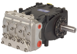
Before initiating load testing, procurement engineers must document the equipment manufacturer's specified performance envelope. For displacement pumps like the Pratissoli PUMP SN7061 L, this includes flow rate (61 L/min), maximum pressure (150 bar), motor power (18.4 kW), and operational speed (1450 rpm). These parameters form the "acceptance criteria"—measurable thresholds that equipment must achieve to pass validation.
Create a baseline testing matrix that includes:
- No-load operation: Run equipment without pressure load for 30 minutes, monitoring motor current draw, vibration levels, and bearing temperature. Current draw should remain 10-15% below rated motor amperage; deviations suggest internal friction or mechanical binding.
- Incremental pressure ramping: Gradually increase system pressure in 20 bar increments, recording flow rate at each pressure step. Plot results on a performance curve to identify pressure-flow characteristics. Real-world curves should match manufacturer specifications within ±5%.
- Sustained load verification: Operate at rated pressure and flow for 4-8 hours continuously, monitoring outlet temperature, pressure ripple, and acoustic emissions. Temperature should stabilize within ±3°C; excessive ripple indicates pump wear or cavitation.
Field Testing Methodology
In Singapore's tropical climate, ambient conditions during testing significantly affect results. Conduct load testing during stable facility operating hours when facility temperature, humidity, and electrical supply remain consistent. Document environmental conditions: ambient temperature (record hourly), relative humidity (critical for motor winding resistance), and incoming fluid temperature.
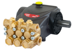
For high-pressure systems like the Interpump PUMP E2B2014 L FL.B3B14 (200 bar), implement graduated pressure testing:
1. Stage 1 (50% rated pressure): Verify equipment operates smoothly at half-rated load. Measure flow rate, motor current, and outlet temperature. Any unusual noise, vibration, or temperature rise indicates potential problems before escalating to full pressure.
2. Stage 2 (75% rated pressure): Extend test duration to 2 hours, monitoring stability. Pressure relief valve setting should activate smoothly at 150-160 bar for this equipment. Verify relief valve response by observing pressure gauge behavior when flow path is blocked—pressure should rise smoothly and relief should activate without chattering.
3. Stage 3 (100% rated pressure): Operate at full specification for 4+ hours. Record instantaneous pressure readings at 5-minute intervals. Calculate pressure deviation as percentage of mean pressure; acceptable variance is typically ±3-5% for positive displacement pumps.
Compressor-Specific Load Testing Considerations
Compressor validation differs from pump testing because discharge pressure builds in sealed systems. Before pressurizing, inspect all safety relief valves and pressure gauges for calibration certification (typically required every 12-24 months in Singapore). Use calibrated digital pressure transducers rather than mechanical gauges for recording; mechanical gauges introduce ±2-3% reading errors that compromise data validity.
For compressed air systems, establish load testing sequence:
1. Pre-pressurization inspection: Verify all isolation ball valves, pressure relief valves, and drain points are accessible and functional. Confirm moisture removal equipment (refrigerated dryers or desiccant dryers) is operational.
2. Gradual pressurization: Ramp air pressure at approximately 0.5 bar per minute to avoid shock loading. Monitor for leaks using ultrasonic leak detection equipment; audible hissing indicates significant leakage points requiring immediate attention.
3. Load stability verification: Once reaching operating pressure, maintain steady state for 2-4 hours. Record compressor auto-start/stop cycling behavior. Cycling frequency should match design specifications; excessive cycling indicates undersized equipment or pressure switch calibration drift.
Performance Acceptance Criteria and Certification Documentation
Defining Measurable Acceptance Standards
Procurement engineers must establish written acceptance criteria before testing begins. For the Interpump PUMP W916 R U.S. (160 bar, 18 L/min), typical acceptance criteria include:
- Flow rate deviation: Measured flow rate must be within ±5% of nameplate specification (17.1-18.9 L/min)
- Pressure accuracy: System must achieve rated 160 bar within ±3 bar (157-163 bar acceptable)
- Motor current draw: Shall not exceed 1.1× rated full-load amperage during sustained operation
- Acoustic emission: Sound level at 1 meter distance shall not exceed 85 dB(A), measured with calibrated sound level meter
- Thermal stability: Outlet fluid temperature shall not exceed manufacturer specification (typically 60°C for industrial pumps) after 4-hour continuous operation
Document acceptance criteria in a Test Protocol Form that references equipment model, serial numbers, test date, environmental conditions, and specific pass/fail thresholds. This formal documentation establishes the baseline for warranty claims and future comparison.
Creating Performance Certification Records
Maintain detailed test records including:
Pressure-Flow Curve Documentation: Record at least 5-7 data points across the operating pressure range. Plot measured values against manufacturer curves; significant deviation suggests internal leakage or wear. For example, if the Interpump PUMP W953 R VALVE shows flow drop of >10% at rated 172 bar compared to factory curves, internal wear or manufacturing defect exists.
Vibration Analysis: Use portable vibration meters to record peak vibration velocity in millimeters per second (mm/s). ISO 20816 standards classify equipment condition:
- Zone A (Good): <2.3 mm/s – acceptable for continued operation
- Zone B (Acceptable): 2.3-7.1 mm/s – monitor condition, plan maintenance
- Zone C (Just Tolerable): 7.1-11.2 mm/s – correct equipment imminently
- Zone D (Unacceptable): >11.2 mm/s – equipment requires immediate repair
Baseline vibration signatures enable predictive maintenance; future elevated vibration indicates bearing wear or misalignment requiring intervention.
Thermal Stability Records: Document outlet fluid temperature at 30-minute intervals throughout load testing. Stable temperature (variation <±2°C) indicates healthy equipment; rising temperature trend suggests internal friction, cavitation, or inadequate cooling system capacity.
Digital Data Logging: Modern equipment validation uses multi-channel data loggers recording pressure, flow, temperature, and motor current simultaneously. This creates comprehensive performance signatures useful for fault analysis if equipment develops problems post-deployment.
Compliance Documentation for Singapore Industrial Standards
Singapore's Workplace Safety and Health Act and equipment regulations require documented proof of equipment safety and performance verification. Maintain validation records including:
- Equipment identification (serial numbers, manufacturing dates)
- Pre-operation inspection checklist completed by qualified technician
- Load testing results with measurements and date stamps
- Comparison against manufacturer specifications with pass/fail determination
- Safety relief valve inspection and setting verification records
- Signatures from conducting engineer and supervising plant manager
Store electronic copies of all validation documentation in centralized procurement system with cross-reference to equipment asset management database. This enables rapid retrieval if equipment fails and warranty disputes arise.
Integration Testing for Multi-Equipment Systems
Coordinating Pumps and Compressors in Complex Operations
Many Singapore industrial facilities operate interconnected pump and compressor networks. System-level validation extends beyond individual equipment testing to verify that multiple pieces function harmoniously without interference.
Pressure balancing: When multiple pump circuits operate in parallel, install pressure relief valves on each circuit sized to maintain balanced pressure. Test by gradually loading individual circuits while monitoring pressure on all branches; pressure differential should not exceed ±5 bar during normal operation.
Flow rate verification: Totalize flow measurements across all pump outlets using calibrated flow meters. Combined flow should equal sum of individual pump specifications within ±3%. Discrepancies indicate calibration errors, meter malfunction, or internal leakage in pump circuits.
Motor electrical load analysis: For facilities with multiple pumps powered from same electrical panel, measure total electrical current draw during simultaneous full-load operation. Verify three-phase current balance (phase-to-phase variance <5%) and that peak demand does not exceed facility electrical service capacity. Unbalanced loading causes motor overheating and premature failure.
Operational Handover and Training Documentation
After successful validation testing, prepare comprehensive handover documentation for operations and maintenance teams:
- Operating procedure manual: Step-by-step startup/shutdown sequences, normal operating ranges, and adjustable parameters (e.g., pressure relief valve settings)
- Maintenance schedule: Recommended fluid change intervals, filter replacement frequencies, and inspection points based on equipment type and application
- Troubleshooting reference: Common fault modes with diagnostic procedures and corrective actions
- Performance baseline data: Test reports, pressure-flow curves, and thermal signatures as reference for future condition assessment
- Spare parts list: Critical components requiring stock inventory based on MTBF (mean time between failure) data
Conduct formal handover training with operations staff, demonstrating equipment startup, parameter monitoring, and basic troubleshooting procedures. This ensures seamless transition from procurement responsibility to operational ownership.
Common Validation Pitfalls and Risk Mitigation
Avoiding Test Environment Artifacts
Laboratory or factory testing conditions rarely reflect actual plant environments. Common validation mistakes include:
Insufficient ambient temperature control: Equipment tested in climate-controlled facilities then deployed in uninsulated Singapore warehouse environments experiences thermal shock. Motor windings expand/contract, seals become brittle, and fluid viscosity changes dramatically. Conduct field validation testing during peak ambient temperature conditions (typically 32-36°C in Singapore) to stress-test seals and motor cooling capacity.
Clean fluid assumptions: Factory testing uses ultra-clean ISO VG 46 hydraulic fluid; Singapore plants often operate with darker, contaminated fluids. Run acceptance testing with actual operational fluid sourced from facility, not pristine factory fluid. Contamination levels >ISO 4406 18/16/13 significantly increase pump wear rates.
Undersized relief valve testing: Relief valves set during factory testing may not perform identically when installed in plant piping systems. Pressure ripple, relief valve chatter, and unstable pressure regulation frequently emerge only during field testing with actual pipe lengths and fittings. Conduct relief valve response testing as part of validation protocol.
Establishing Contingency Procedures
If equipment fails acceptance testing, procurement engineers must have documented decision procedures:
- Minor variance (±5-10% performance shortfall): Investigate root cause (e.g., fluid viscosity drift, pressure gauge calibration). Conduct repeat testing under controlled conditions; if variance persists, escalate to equipment supplier with formal test reports as evidence.
- Significant failure (>10% performance shortfall): Halt operational deployment. Request equipment replacement or formal credit from supplier. Document all testing evidence and communication with supplier for warranty record.
- Safety-critical failures (relief valve malfunction, excessive vibration, abnormal temperature): Immediately isolate equipment from service. Do not attempt operational use. Engage 3G Electric's technical support or equipment manufacturer for failure analysis and replacement planning.
Maintain documented decision log showing all validation test results, pass/fail determinations, and equipment disposition (approved for service, conditioned approval, or rejection). This audit trail proves due diligence in procurement oversight and protects facility management from liability if equipment subsequently fails.