Why Right-Sizing Pumps & Compressors Matters for Your Bottom Line
Most plant managers inherit pump and compressor systems that were either oversized during initial installation or undersized after production capacity expanded. Oversized equipment runs inefficiently, consuming 20-40% more energy than necessary while operating in the low-efficiency zone of its performance curve. Undersized equipment cavitates, struggles under peak loads, and fails prematurely—creating unplanned downtime that costs far more than equipment replacement.
After 35+ years supplying industrial equipment across Southeast Asia, 3G Electric has seen firsthand how right-sizing decisions compound over time. A pump operating at just 60% of its rated capacity can waste ₹50,000-₹200,000 annually in excess energy costs alone. Scale that across multiple systems in a 24/7 plant, and the financial impact becomes substantial.
This guide walks you through the practical steps to right-size pumps and compressors based on your actual operational profile, not vendor recommendations or historical specifications. You'll learn to calculate your true flow and pressure requirements, evaluate equipment options against real-world duty cycles, and make decisions that balance capital cost with long-term operational efficiency.
Step 1: Calculate Your Actual Flow and Pressure Requirements
Determine Operating Flow Rate
Flow rate is the volume of fluid your system needs to move per unit time, typically measured in liters per minute (L/min) or gallons per minute (GPM). Many plant managers use installed pump nameplate capacity as their requirement, but this is often wrong. Your actual requirement is determined by process demand, not equipment capability.
Start by identifying your three distinct operating scenarios:
- Peak demand: Maximum simultaneous flow during production (rarely sustained continuously)
- Normal operating demand: Typical daily production flow (70-80% of time)
- Standby/relief demand: Minimum flow when system is idle or in standby (circulation, cooling)
For a typical hydraulic system serving multiple actuators, don't simply add all individual flow requirements. Document how many actuators actually operate simultaneously under normal conditions versus peak conditions. If your system serves 10 circuits rated at 20 L/min each, but only 4-5 circuits run simultaneously, your true normal demand is 80-100 L/min, not 200 L/min.
Practical example: A Singapore food processing plant operated a primary hydraulic system with a 150 L/min pump selected for worst-case peak demand. Analysis revealed 95% of daily operation required only 85-95 L/min, with peak demand occurring 2-3 hours monthly. A smaller 110 L/min pump with a standby relief was installed, reducing annual energy costs by ₹1,80,000 while actually improving system responsiveness during peak periods through better pressure regulation.
Determine Required System Pressure
System pressure must overcome resistance in your application—actuator load, line friction, component pressure drops, and safety margin. The critical mistake is sizing to maximum pressure the application could see, rather than the pressure required for normal operation.
Measure or calculate:
- Load pressure: Force required divided by actuator area (bar or psi)
- Line friction loss: Typically 10-20% of load pressure for properly sized piping
- Component pressure drops: Valves, filters, heat exchangers (vendor data)
- Safety margin: 10-15% above calculated pressure for transients and future capacity
Many systems run at unnecessarily high pressures because original specifications included worst-case assumptions. If your process pressure requirement is 120 bar but your relief valve is set to 160 bar, you're paying energy cost for 40 bar of unused capacity.
Practical example: An industrial cleaning equipment supplier in Singapore discovered their pump was rated for 250 bar, but actual nozzle pressure requirement was only 180 bar. System relief was set at 200 bar. Switching to a lower-pressure-rated pump (180 bar duty) with proper relief setting reduced energy consumption by 25% without affecting spray pattern or cleaning performance.
Step 2: Match Equipment Specifications to Your Duty Cycle
Evaluate Motor Power Requirements
Pump and compressor power consumption is directly proportional to flow and pressure. The formula is simple: Power (kW) = (Flow × Pressure) / (600 × Efficiency)
For a hydraulic pump moving 100 L/min at 120 bar with 90% efficiency: Power = (100 × 120) / (600 × 0.90) = 22.2 kW
Here's the critical insight: If you operate this pump at only 80 L/min and 100 bar (common during lower-demand hours), actual power required drops to: Power = (80 × 100) / (600 × 0.90) = 14.8 kW
Yet if your pump is fixed-displacement, it will still draw closer to 22 kW from the motor, with the excess energy dissipated as heat through the relief valve. This is waste.
Right-sizing strategy for variable-demand operations:
- Fixed-displacement pump + relief: Use only if demand is consistent. Size for normal operating flow/pressure. Cost-effective initially but inefficient for varying loads.
- Variable-displacement pump + pressure compensator: Automatically adjusts displacement to maintain system pressure. Ideal for systems with 20-50% demand variation. Typical energy savings: 15-30%.
- Dual-pump systems: Small gear pump for low-flow standby, large pump for peak demand. Effective for systems with extended low-demand periods.
For the Interpump PUMP E2B2014 L FL.B3B14 compact industrial pump, rated at 14 L/min and 200 bar with 5.37 kW motor, this specification is ideal for precision applications requiring consistent mid-range flow. If your actual demand averages 10 L/min, this pump will operate efficiently near its design point. If demand averages 8 L/min or varies between 5-14 L/min, you might benefit from a variable-displacement unit instead.
Consider Compressor Duty Cycles
Air compressors present unique right-sizing challenges because demand is often intermittent. Many plant managers oversize based on peak CFM (cubic feet per minute) requirements, resulting in compressors that cycle on/off frequently, reducing efficiency and increasing wear.
Analyze your compressed air demand profile:
- Peak instantaneous demand: Maximum CFM when all tools/processes operate simultaneously (occurs briefly)
- Average demand: Sustained CFM over a typical 8-hour production shift
- Idle-time leakage: CFM lost through system leaks when equipment isn't running
Compressor sizing should target average demand plus 10-15% safety margin, not peak demand. If peak demand exceeds average by >25%, install a secondary smaller compressor or compressed air storage to handle transients without oversizing the primary unit.
Practical example: A Singapore automotive parts manufacturer operated a 37 kW (50 hp) air compressor delivering 280 CFM at 7 bar. Peak demand analysis showed only 180 CFM average during production, with 200 CFM peaks lasting <5 minutes monthly. A dedicated 22 kW (30 hp) compressor delivering 140 CFM was installed alongside a 500-liter buffer tank. The primary unit now runs continuously at peak efficiency, the secondary handles transient demand, and annual energy costs dropped by ₹3,20,000.
Step 3: Evaluate Specific Product Options Against Your Requirements
Intermittent-Duty Applications
For applications requiring precise pressure and lower flow, the Delta Pump VM3 RL 2.4 oil burner fuel pump unit offers integrated solenoid valve control with factory-set pressure of 20 ±0.3 bar. This pump is ideal for fuel delivery, lubrication systems, or process applications where precise pressure regulation is critical. The 3500 rpm operating speed and 10-25 bar range make it suitable for lower-volume, moderate-pressure duties.
When to specify this: Intermittent fuel delivery, burner ignition systems, or automatic lubrication circuits where flow consistency matters more than volume.
High-Pressure, Lower-Flow Industrial Duty
The Interpump PUMP E2B2014 L FL.B3B14 14 L/min at 200 bar is engineered for compact installations requiring high pressure in confined spaces. At 5.37 kW and 1450 rpm, this pump operates efficiently across industrial hydraulic applications—pressure testing, material processing, precision molding.
The 7 kg weight and 225 mm footprint make it suitable for mobile equipment, vehicle-mounted systems, or retrofit applications where space is limited. Use this when your actual flow requirement is 10-16 L/min at 180-220 bar pressure.
Mid-Range Industrial Hydraulic Systems
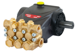
The Interpump PUMP W953 R VALVE W/O RAILS 11.5 L/min at 172 bar delivers reliable performance at 1750 rpm with 3.67 kW power consumption. Weighing just 7.9 kg, this pump fits applications requiring 10-13 L/min sustained flow—typical for single-circuit hydraulic systems, small presses, or auxiliary hydraulic power units.
The integrated relief valve option (included in SKU W00953V-100) simplifies system design and reduces component count. Suitable for plant retrofit applications and OEM equipment.
High-Volume Continuous Duty
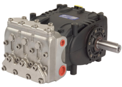
For sustained operation requiring flow above 50 L/min, the Pratissoli PUMP SN7061 L 61 L/min at 150 bar is engineered for all-day continuous duty. The 18.4 kW motor at 1450 rpm delivers consistent displacement with proven reliability in hydraulic fluid transfer, injection molding, and industrial processing applications.
At 150 bar rated pressure, this pump trades maximum pressure for volume capacity—ideal when your system requires high flow at moderate pressures. Operating at 1450 rpm reduces noise and heat generation compared to higher-speed alternatives, extending fluid life and component durability.
Variable-Demand Systems with Peak Requirements
The Interpump PUMP W916 R U.S. W/O RAILS 18 L/min at 160 bar is specified for systems requiring robust performance across varying loads. At 1750 rpm with 5.51 kW power, this pump accommodates applications with intermittent peak demand—test stands, material handling, or production systems with cyclical operation.
This pump is frequently paired with pressure-compensated systems and accumulator technology to smooth demand spikes, improving overall system efficiency.
Step 4: Calculate True Cost of Ownership
Don't select equipment based on purchase price alone. Energy cost dominates pump and compressor lifecycle expense.
Five-year ownership cost calculation:
1. Equipment cost: Pump, motor, controls, installation (typically 10-15% of five-year expense)
2. Energy cost: (kW × operating hours × ₹/kWh × efficiency factor)
3. Maintenance cost: Seals, fluid replacement, filter changes (typically 5-10% annually)
4. Downtime risk: Estimated cost of unplanned failures during peak production
5. Replacement cost: Residual value at end of five years
Example calculation for oversized pump:
- Equipment cost: ₹4,00,000
- Annual energy: 30 kW × 5,000 hours × ₹8/kWh = ₹12,00,000/year × 5 years = ₹60,00,000
- Maintenance: ₹1,50,000 over five years
- Total five-year cost: ₹65,50,000
- Equipment cost: ₹3,00,000
- Annual energy: 18 kW × 5,000 hours × ₹8/kWh = ₹7,20,000/year × 5 years = ₹36,00,000
- Maintenance: ₹1,50,000 over five years
- Total five-year cost: ₹40,50,000
This is where 3G Electric's experience matters. Our supply relationships across 35+ years in Southeast Asia allow us to source pumps and compressors optimized for your specific duty cycle, not generic catalog selections.
Implementation: Moving from Analysis to Action
Audit Your Current Systems
Begin with your three largest or most critical pump/compressor systems:
1. Document nameplate specifications (flow, pressure, power, rpm)
2. Measure actual operating pressure during peak and normal operation using calibrated gauges
3. Monitor motor amperage draw or power consumption (underloaded motors draw proportionally less current)
4. Interview operators on actual flow requirements for their production cycles
5. Calculate efficiency ratio: (required power) ÷ (nameplate power)
If your efficiency ratio is below 0.75, right-sizing will likely reduce energy costs by 15-30%.
Specify Replacement or New System Installations
When sourcing new pumps or compressors:
1. Provide 3G Electric with three specification parameters: peak flow requirement, normal operating flow, and required system pressure
2. Disclose your duty cycle percentage: What % of time at peak? Normal? Standby?
3. State energy cost priorities versus capital cost constraints
4. Specify required motor frame size or mounting configuration
5. Request efficiency comparison between fixed-displacement and variable-displacement options
Our technical team can then recommend specific SKUs with confidence that they'll operate in the efficient portion of the performance curve throughout your actual duty cycle.
Plan for Future Expansion
Right-sizing means matching today's requirement, not tomorrow's potential. If you anticipate 20% production growth within three years, specify equipment for that future demand—not current demand. The incremental cost of oversizing by 20% is far less than replacing equipment in three years.
However, don't oversize for speculative growth. If expansion depends on market conditions outside your control, size for current demand and commit to upgrade timelines based on actual business results.