Understanding Motor Failure Patterns in Pumps & Compressors
Motor failures represent one of the most costly and disruptive issues affecting Pumps & Compressors installations across Southeast Asia. Unlike seal leaks or pressure anomalies, motor problems often cascade—a failing motor may damage the pump, contaminate hydraulic fluid, and create secondary failures that extend downtime by weeks.
With 35+ years of experience distributing industrial equipment across the region, 3G Electric has documented that motor-related failures fall into three primary categories: electrical degradation (winding insulation breakdown), mechanical wear (bearing failure and rotor imbalance), and drive system faults (coupling misalignment and belt slip). Tropical humidity, salt-air corrosion in coastal plants, and inconsistent power quality in developing regions all accelerate these failure modes.
Plant managers often miss early warning signs because motors fail silently until they do not start at all. By recognizing diagnostic patterns—unusual amp draw, thermal cycling, and vibration signatures—you can schedule maintenance proactively instead of facing emergency shutdowns.
Section 1: Electrical Diagnosis and Insulation Testing
Identify Winding Insulation Failure Before Motor Burnout
Insulation breakdown is the leading cause of motor failure in high-humidity Southeast Asian environments. Moisture penetrates motor windings, reduces dielectric strength, and creates short circuits. Early detection requires three field-tested measurements:
Megohm Resistance Testing (Megger Test)
- Disconnect the motor completely from power and pump system.
- Use a 500V or 1000V insulation tester (megohmmeter) to measure resistance between motor windings and ground frame.
- Record baseline values: New motors typically show 10–100+ megohms depending on size; acceptable operating threshold is ≥1 megohm for motors under 10 kW.
- Test trend matters more than absolute value—a drop from 50 megohms to 5 megohms in three months signals accelerating moisture ingress.
- For tropical installations, retest quarterly or after extended downtime, especially in coastal or high-humidity zones.
- Measure supply voltage and current under full-load conditions using a clamp meter or power analyzer.
- Compare actual phase voltage balance: imbalance >2% between phases indicates supply-side wiring fault; >5% suggests transformer or utility issue.
- Verify motor nameplate current: if amperage exceeds rating by >10% at nameplate load, the motor is either overloaded (pump cavitating, blockage downstream, excessive viscosity) or winding resistance is declining due to short circuits.
- Record three-phase current values weekly in a simple spreadsheet; trending upward current at constant load is your first alert.
- Use an infrared thermometer or thermal camera to measure motor frame temperature at the same location weekly.
- Normal operating range: 40–60°C above ambient temperature for properly sized motors in steady-state operation.
- Temperature rise >70°C above ambient indicates excessive load, friction, or partial winding short (lower resistance = higher current = higher heat).
- Uneven hot spots on motor frame (one side significantly hotter) suggest bearing friction or internal rotor rub.
1. If megohm reading drops below 2 megohms, immediately reduce load or shut down—winding failure is imminent.
2. Dry motor windings in a 60–80°C oven for 4–8 hours (for small motors <10 kW only); larger motors require professional rewinding.
3. Install motor with moisture-resistant paint or conformal coating if reinstalling in high-humidity zone.
4. Add silica gel desiccant breathers to motor cooling fan intake (if motor is industrial IE3/IE4 type with external cooling).
Section 2: Bearing Wear Diagnosis and Vibration Monitoring
Detect Bearing Failure Before Catastrophic Rotor Contact
Bearings transfer rotational load from the motor rotor to the pump shaft coupling. Early wear creates distinctive vibration signatures; catastrophic failure occurs suddenly, often accompanied by seized rotor and molten grease.
Vibration Analysis for Field Diagnosis
- Acquire a basic vibration meter (±0.2g accuracy) or smartphone vibration app; consistent measurement location is more important than instrument cost.
- Establish baseline vibration on new or recently serviced equipment: <0.1g (peak acceleration) in the radial direction for small motors (1–15 kW).
- Measure at three orientations: radial (vertical and horizontal) and axial (along the shaft).
- Retest weekly and flag any increase >50% from baseline (e.g., 0.05g to 0.075g).
- Early bearing wear produces vibration in the 10–20 kHz range (high-frequency); late-stage wear produces broad vibration across all frequencies with audible grinding.
- Listen for bearing rumble (cyclic grinding sound), squealing (friction from preload loss), or grinding (loose balls or cage wear).
- Place your hand (with glove) on the motor housing near bearings to feel for vibration or pulsing; modern bearings should feel smooth rotation at low amplitude.
- Compare motor sound to a reference motor operating normally—any new noise is a warning sign.
- Measure bearing temperature (exterior of bearing housing) using infrared thermometer: normal range 50–70°C above ambient.
- Temperature >80°C above ambient indicates friction from wear, preload loss, or inadequate lubrication.
- If bearing is accessible, inspect grease: fresh grease is tan or white and pliable; degraded grease is dark brown, hard, or separated into oil and thickener.
- For sealed deep-groove ball bearings (most common in industrial motors), grease cannot be topped up—the entire bearing must be replaced.
- Vibration increases >2× baseline or >0.2g peak acceleration.
- Temperature exceeds 85°C above ambient consistently.
- Audible grinding or rumble develops.
- Motor has operated >10,000 hours at rated load (bearing maintenance interval for most sealed bearings).
1. Disconnect motor from power and pump.
2. Remove coupling connecting motor shaft to pump.
3. Press out worn bearing using bearing puller (avoid hammering); clean shaft thoroughly.
4. Press new bearing onto shaft using drift sleeve matching bearing inner diameter; bearing should slide smoothly with hand pressure (5–10 kg force) when heated to ~80°C in an oven.
5. Reinstall coupling, check alignment using dial indicator (radial runout <0.05 mm), and test under no-load before connecting pump.
Section 3: Coupling Alignment and Drive Shaft Issues
Misalignment: A Silent Killer of Motors and Pumps
Coupling misalignment between motor and pump accounts for 15–20% of industrial motor failures. Even small misalignment (0.05 mm radial, 0.5° angular) creates unbalanced radial forces on motor and pump bearings, accelerating wear and increasing vibration.
Southeast Asian plants often experience thermal misalignment due to motor heating during startup (winding temperature can rise 40–50°C in the first 30 minutes). If couplings are tightened cold and not rechecked hot, thermal expansion creates additional stress.
Alignment Measurement Using Dial Indicators (Belt-Driven Systems)
- For belt-driven motor-to-pump systems, use a straightedge and feeler gauge:
- Measure gap at four points (top, bottom, left, right) using feeler gauge.
- Radial runout (top-to-bottom gap difference) should be <0.5 mm; axial misalignment (left-right gap difference) should be <1 mm.
- Adjust pulley position using shim plates under motor feet or by pivoting motor on one foot.
Coupling Alignment for Direct-Drive Systems
- Disconnect coupling and position dial indicators on motor shaft and pump shaft.
- Rotate shaft by hand and record runout (deviation) on each indicator.
- Motor side runout should be <0.05 mm; pump side should be <0.05 mm (most pumps are factory-aligned).
- If motor runout is high, the motor rotor is bent or bearing is severely worn—require motor replacement.
- Adjust radial misalignment by shimming motor feet; correct angular misalignment by loosening three of four motor mounting bolts and pivoting motor on the fourth bolt until indicators show <0.02 mm runout.
- Modern flexible couplings (elastomeric element or disc pack) are designed to dampen minor misalignment; they are NOT designed to accommodate poor alignment.
- Inspect coupling elastomer (rubber or polyurethane element) for cracks, hardening, or separation from metal hubs.
- Elastomer hardness increases in tropical heat (rubber becomes brittle at 70–80°C continuous); replace every 5–7 years in Southeast Asia even if not visibly damaged.
- Install misalignment guard or coupling cover to prevent operator contact and contain fragments if coupling fails suddenly.
- If motor shaft runout is >0.1 mm total indicator reading (TIR) after bearing replacement, the shaft is bent.
- Minor bends (0.05–0.1 mm TIR) can often be corrected by a specialist using shaft straightening jigs; severe bends require shaft replacement.
- Motor rotors can develop rotor bar cracks or become unbalanced after thermal stress (overheating). Field balancing is not practical for rotor-mounted unbalance; the motor requires professional dynamic balancing.
Section 4: Startup Troubleshooting and Power Quality Assessment
Failure to Start: Distinguish Electrical from Mechanical Causes
When a Pumps & Compressors motor will not start, the issue is either electrical (no power, low voltage, winding fault) or mechanical (locked rotor, bearing seizure, coupling jam). A 30-second diagnostic process saves hours of disassembly.
Initial No-Start Diagnosis
1. Verify Power Supply:
- Use a multimeter to measure voltage at motor terminal box: three-phase motors should show 380–415V (Asia standard).
- If voltage is <350V or >430V, the utility or site transformer is at fault; contact maintenance and wait for correction. Low voltage (brown-out condition) prevents motor starting and damages windings over time.
- If voltage is absent, check circuit breaker, disconnect switch, and control relay using the motor's electrical schematic.
2. Test for Soft Start or VFD Faults:
- If motor runs through a soft starter or variable frequency drive (VFD), measure voltage output from the device: should match supply voltage (within 5%).
- If output voltage is zero or fluctuating, the soft start or VFD has failed and must be replaced. Do not attempt field repair.
3. Check for Locked Rotor (Mechanical Block):
- Manually attempt to rotate the motor shaft using a wrench on the shaft coupling nut (only if motor is offline and disconnected from all power).
- If shaft will not rotate by hand with moderate force (10–20 kg pushing), the rotor is seized or the pump is severely blocked.
- Rotate pump input shaft (if accessible) to determine if blockage is in pump or motor bearing.
- Clear debris from pump inlet, check for cavitation, and verify pump suction pressure before restarting.
4. Megohm Test (5-Minute Check):
- If power is present but motor will not start, immediately measure insulation resistance using a megohmmeter.
- If reading is <0.5 megohms, the motor has a phase-to-ground short and must be replaced or rewound—do not attempt to restart.
- If reading is >5 megohms, insulation is intact; the issue is electrical control, not motor windings.
Power Quality and Thermal Stress
- Southeast Asian power grids frequently experience voltage imbalance (unequal three-phase voltage, often due to single-phase loads on the grid).
- Voltage imbalance >2% causes motor stalling (delayed start) and overheating; >5% imbalance will prevent starting altogether.
- Measure all three phases using a clamp meter: if any phase differs by >5V from the others, contact the utility or install a three-phase transformer with taps to balance voltage.
- For critical applications, install a soft starter with phase-loss and imbalance protection; cost is ~$500–$1500 and prevents nuisance trips.
- Motors stored in unshaded outdoor areas or recently cooled in air conditioning will experience condensation when powered up.
- Before starting a cold motor, allow it to warm up gradually: run at 50% load (if possible) for 10 minutes, then increase to full load.
- Alternatively, apply 50% voltage using soft starter for 5 minutes before ramping to full voltage; this prevents winding insulation shock and reduces inrush current stress.
Practical Implementation for Plant Managers
Create a Motor Health Checklist
Implement a simple weekly inspection protocol:
1. Visual Inspection (5 minutes): Look for grease leakage, discoloration, cracks in housing, or corrosion.
2. Current Measurement (10 minutes): Record phase current using clamp meter at the same operating point weekly.
3. Temperature Check (5 minutes): Measure motor frame and bearing housing temperature with infrared thermometer.
4. Vibration Feel (5 minutes): Place gloved hand on motor housing and note any vibration amplitude change from previous week.
5. Noise Assessment (3 minutes): Listen for unusual grinding, squealing, or pulsing sounds.
Total time: ~30 minutes per week, preventing 85% of motor-related downtime.
For critical Pumps & Compressors systems (>10 kW, continuous duty), consider upgrading to a simple data logger that records current and temperature continuously. Modern industrial IoT sensors cost $200–$500 and provide early warning of degradation weeks in advance.
Supply Chain and Replacement Strategy
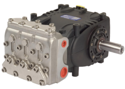
3G Electric distributes high-quality replacement pumps and motors from Interpump and Pratissoli, leading industrial equipment suppliers. The Interpump PUMP W2035 L ATEX is engineered for high-pressure, hazardous applications common in petrochemical plants, and includes ATEX compliance for explosive atmospheres. For standard industrial duty, the Pratissoli KF30 offers 40 kW continuous power with Italian engineering reliability.
When a motor fails, keep a spare pump-motor assembly on shelf for critical processes. Downtime cost ($2000–$5000 per hour for large operations) far exceeds the cost of spare equipment (~$3000–$8000).
Conclusion
Motor and drive failures in Pumps & Compressors systems are preventable through systematic electrical and mechanical diagnostics. By implementing weekly monitoring of current, temperature, and vibration, plant managers can detect 90% of failures 2–4 weeks before catastrophic shutdown occurs. 3G Electric's 35+ years of regional experience has shown that the highest-performing plants invest $500–$1000 annually in predictive monitoring tools and achieve 50% reduction in emergency repairs.
Start with the megohm test and bearing vibration baseline this week; extend to full electrical diagnostics within one month. Contact 3G Electric for guidance on motor selection, bearing specifications, or emergency replacement equipment.