Understanding Pumps & Compressors Priming Fundamentals
Pumps & Compressors require proper priming—the removal of air from inlet lines and pump chambers—to establish continuous fluid column from source to discharge. Without successful priming, pumps cannot develop rated pressure or flow, leading to system failure and costly downtime.
With over 35 years of experience supplying industrial equipment globally, 3G Electric has supported plant managers through thousands of pump commissioning and troubleshooting scenarios. Priming failures remain among the most common intake-side issues affecting high-pressure hydraulic systems, condensate drainage networks, and fluid transfer applications across diverse industries.
When priming fails, several cascading problems occur: pump cavitation damages internal components, flow drops to zero or becomes erratic, pressure cannot build, and motor current spikes as the pump works harder to move air instead of fluid. Understanding priming mechanics—atmospheric pressure limits, inlet line design requirements, foot valve functionality, and venting principles—enables rapid diagnosis and resolution.
Section 1: Diagnosing Priming Failures and Intake-Side Air Entrainment
Identifying Priming Problem Indicators
Plant managers should monitor these early warning signs of intake-side dysfunction:
- No pressure development: Pump motor runs but discharge pressure remains near zero; typical across centrifugal and positive-displacement designs
- Cyclic pressure oscillation: Pressure fluctuates wildly, indicating periodic air pockets entering pump inlet
- Audible cavitation noise: Grinding, crackling, or popping sounds from pump discharge, caused by vapor bubbles collapsing as fluid accelerates
- Reduced flow with increased motor current: System flow drops while motor amperage climbs above nameplate rating—pump expends energy moving air
- Vapor or foam in discharge fluid: Aerosol-like discharge indicates entrained air passing through system, reducing lubrication film integrity
- Slow pressure ramp-up at startup: Takes 30+ seconds to reach operating pressure instead of 5-10 seconds; signals partial air entrainment
Root Cause Analysis Framework
Intake-Side Pressure Limitation: Atmospheric pressure (101.3 kPa at sea level) limits pump inlet capability. Fluid columns cannot be drawn upward more than approximately 10.3 meters (33.8 feet) from source reservoir to pump inlet. Installations exceeding this height require supply-side pressurization or submerged inlet positioning.
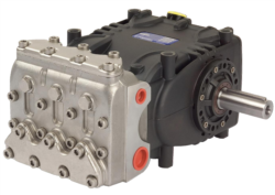
Foot Valve and Strainer Blockage: Check valves at reservoir inlets prevent backflow but accumulate particulates. Partially blocked foot valves restrict inlet flow below pump demand, creating partial vacuum that draws air through micro-leaks in intake piping. High-performance systems like the Pratissoli KF30 high-pressure industrial pump delivering 106 L/min at 200 bar demand unrestricted inlet flow; any restriction causes priming loss within seconds.
Intake Line Design Defects: Undersized inlet piping creates backpressure that prevents adequate fluid supply. Industry standard: inlet line velocity should not exceed 0.6 m/s (2 feet/second). For example, a pump requiring 45 L/min intake flow needs minimum 2-inch (50 mm) diameter inlet hose. Kinked, twisted, or collapsed flexible hose sections similarly restrict inlet flow and create vacuum conditions that draw air through seals.
Seal and Fitting Leakage: Intake-side connections at pump inlet flanges, sight glass fittings, or pressure-relief bypass lines allow air ingestion. Even hairline cracks in inlet manifold galleries introduce micro-bubbles that accumulate into larger vapor pockets. Centrifugal pump designs like the Interpump WW90 L with integrated valve operating at 90 bar require absolutely sealed intake ports.
Reservoir Venting Issues: Improperly sealed or plugged vent lines prevent atmospheric pressure from pushing fluid into pump inlet. If reservoir develops negative pressure, intake-side cavitation occurs even with proper suction head. Conversely, excessive positive pressure from compressed air in sealed reservoirs can prevent priming during initial startup.
Section 2: Systematic Priming and Intake Troubleshooting Procedures
Step-by-Step Diagnostic Protocol
Step 1: Verify System Static Conditions Before Startup
- Confirm inlet reservoir fluid level is above pump inlet port height; minimum 150 mm above suction line intake
- Inspect inlet hose for visible kinks, crushing, or deformation
- Check all intake-side fittings and connections for seepage or air bubble evidence
- Verify foot valve moves freely (if equipped); remove and visually inspect for debris
- Test reservoir vent cap—should feel slight suction when sealed and released
- For systems with isolation ball valves on inlet line, close discharge shutoff valve
- Loosen pump inlet port bleed screw or high-point vent (usually 1/4-inch NPT)
- Attach clear plastic tube to bleed port directed into reservoir
- Open inlet isolation valve and manually hand-prime pump using priming pump or gravity feed until steady fluid stream (no air bubbles) flows from vent
- Close bleed screw firmly; do not overtighten (risk of port stripping)
- Start system at minimum motor speed (if variable frequency drive equipped); otherwise manual speed reduction via belt/pulley if accessible
- Observe bleed port region immediately—slight fluid seepage indicates successful priming
- Monitor discharge pressure rise: should reach 50% rated pressure within 5 seconds
- Listen for cavitation noise cessation as pressure builds
- Gradually increase motor speed over 10-15 seconds to full operational RPM
- If pressure remains below 10% rated value after 30 seconds: priming failure confirmed
- Install compound gauge on pump discharge (0-15 PSI range); reading should show positive pressure immediately
- If discharge gauge shows vacuum or zero pressure: pump is pulling air, not fluid
- Connect low-pressure gauge (0-5 PSI) to inlet port; reading should show positive pressure 2-4 PSI, indicating adequate inlet supply
Advanced Intake Troubleshooting for High-Performance Systems
High-pressure positive-displacement pumps like the Interpump PUMP W2035 L ATEX delivering 35 L/min at 200 bar and Pratissoli SN7045 L operating at 210 bar with 18.4 kW motor require exceptionally clean, air-free inlet conditions.
Intake Filtration Verification: High-speed pumps damage internal components (swashplate, pistons, valve blocks) within hours if even microscopic air bubbles reach displacement chambers. Install 200-micron suction strainer; pressure drop across strainer should not exceed 0.3 bar during normal operation. If differential pressure exceeds 0.5 bar, strainer requires replacement.
Inlet Pressure Maintenance: Verify pump inlet manifold pressure using low-range pressure transducer (0-10 bar):
- At rated flow: inlet pressure should remain 1.5-3.0 bar positive
- If inlet pressure drops below 0.5 bar: air is entering the system
- If inlet pressure rises above 5.0 bar: downstream backpressure is excessive; inspect discharge lines for restrictions
Section 3: Intake Line Redesign and Preventive Solutions
Intake System Architecture Best Practices
Inlet Line Sizing and Material Selection:
- Calculate required inlet hose ID using formula: ID (mm) = √(4 × Flow L/min ÷ (π × 60 × 0.6))
- For 45 L/min flow: ID = √(4 × 45 ÷ (π × 60 × 0.6)) = 9.8 mm; use 1/2-inch hose (12.7 mm ID) minimum
- For 106 L/min (KF30 pump): ID = 14.2 mm; use 5/8-inch hose (15.9 mm ID) minimum
- Use low-collapsibility hose rated EN 856 4SP or equivalent; avoid garden-style hoses that collapse under suction
- Install 200-micron strainer basket upstream of foot valve; easier replacement than foot valve itself
- Ensure foot valve seat clearance prevents silt accumulation; submerge valve inlet 150-300 mm below minimum reservoir fluid level
- Monthly visual inspection: lift reservoir lid and observe foot valve for visible debris accumulation
- Maintain minimum 5-minute fluid dwell time before pump intake; larger reservoirs improve air desorption
- For 45 L/min pump operation: minimum reservoir volume = 45 L/min × 5 min = 225 liters (60 gallons)
- Position pump inlet 300 mm minimum from reservoir bottom to avoid sludge and particulate intake
- Install baffles separating return-line entry from intake region; prevents vortex formation that draws air
- Install 5-micron sintered bronze reservoir vent filter; allows air exchange while capturing atmospheric particulates
- For sealed systems, use bladder accumulator (0.5-1.0 liters for typical systems) sized to maintain 1-2 bar positive inlet pressure during pump idle periods
- If system includes pressure-relief bypass to reservoir, install separate return line not submerged below minimum fluid level; prevents back-pressurization of intake circuit
Operational Maintenance Program
Daily Shift Checks:
- Inspect for foam or air bubbles in reservoir sight glass
- Listen at pump inlet line for sucking sounds (indicates air leak)
- Note startup time to reach operating pressure; increases above 10 seconds signals developing intake restriction
- Verify inlet line remains fully supported with no new kinks or sagging
- Check foot valve/strainer area for debris accumulation or color changes in fluid
- Operate system through full pressure range; note smooth pressure transitions without cycling or chatter
- Clean or replace inlet strainer basket; document pressure drop measurements
- Inspect pump inlet port flange gasket; replace if visible distortion or leakage detected
- Verify all intake-side fittings torque specification (typically 20-35 Nm depending on port size); re-torque to prevent micro-leaks
- Test reservoir vent functionality; confirm filter element is dry (not saturated with moisture)
Section 4: Condensate Pump Integration and Specialty Intake Applications
HVAC Condensate Drainage System Priming
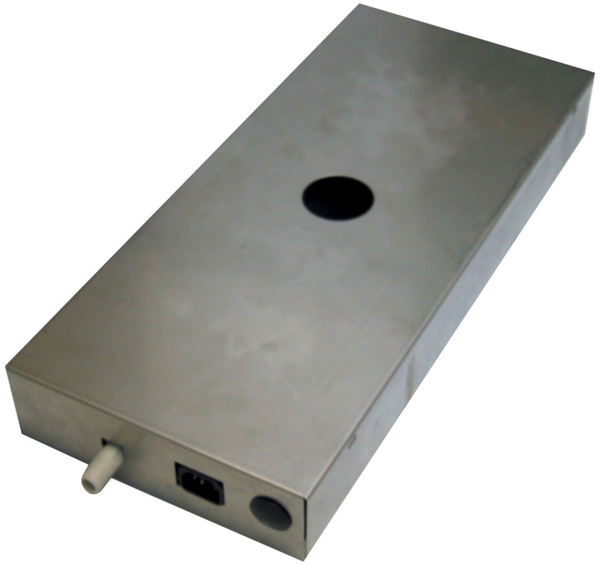
The Clima Concept condensate pump with 5-liter reservoir operates on different priming principles than high-pressure industrial systems. Condensate pumps must overcome gravity lift (maximum 10 meters) and discharge pressure against chilled water line backpressure (typically 0.5-2.0 bar).
Condensate-Specific Priming Challenges:
- Water collected in HVAC coil pans can contain microbial films, algae, and mineral deposits that accumulate in pump inlet valve seats
- Temperature cycling between cold coil operation (4-7°C) and warm discharge (ambient) causes condensation in vent lines, creating water seal that blocks air exchange
- Seasonal startup (after months of idle winter operation in temperate climates) often requires aggressive priming due to stagnant water in pump chambers
1. Locate pump reservoir and verify water level at minimum 2 cm above internal intake tube opening
2. Locate large reservoir lid or access port; remove and inspect float switch mechanism for corrosion
3. Manually fill reservoir with clean distilled water (removes dissolved air) until water overflows from small vent port
4. Wait 30 seconds for air bubbles to escape; top off water level again
5. Close vent port; start pump motor
6. If pump does not discharge water within 10 seconds, manually activate pump by tilting float switch arm downward (simulates high-level condition)
7. Once discharge begins, allow pump to run for 30 seconds to completely purge inlet lines
Transfer Pump Integration Intake Considerations
When integrating multiple pump systems (e.g., primary high-pressure pump with tertiary fluid transfer pump), intake sequencing becomes critical. If primary pump draws fluid from reservoir before transfer pump establishes pressure, cavitation occurs in transfer pump discharge port.
Multi-Pump System Priming Sequence:
1. Prime lowest-pressure system first (transfer pump at atmospheric inlet pressure)
2. Once transfer pump establishes 1-2 bar discharge pressure, verify intake pressure at primary pump exceeds 3.0 bar
3. Then start primary high-pressure pump (e.g., Pratissoli SN7045 L at 210 bar)
4. Stagger startup intervals by minimum 15 seconds to prevent simultaneous intake demand spikes
---
Troubleshooting Decision Tree
If pump starts but produces no pressure:
- Check inlet strainer for blockage (highest probability)
- Verify reservoir vent cap is not plugged
- Inspect intake line for visible collapse or kinking
- Confirm pump inlet port is not air-locked (bleed screw procedure required)
- Partial priming loss is occurring; likely micro-leak in intake fitting
- Tighten all NPT connections on pump inlet manifold
- Remove and inspect pump inlet port gasket; replace if compressed or discolored
- Intake restriction (foot valve or strainer) combined with downstream pressure relief activity
- Clean or replace strainer; inspect discharge pressure-relief valve operation
- Air bubbles are present in discharge but pump priming succeeded
- Problem is likely downstream: check for leaks in discharge line before main system pressure gauge
- Verify pump outlet port fitting connections; tighten if seepage observed
Summary: Priming Excellence and System Reliability
Successful Pumps & Compressors priming depends on three fundamental elements: (1) adequate inlet fluid supply at positive pressure, (2) complete air removal from pump chambers via manual bleeding, and (3) sustained air-free operation through sealed intake design and preventive maintenance. Plant managers who implement the systematic diagnostic procedures outlined above—combined with thoughtful intake line architecture and regular maintenance protocols—achieve 95%+ first-start reliability and extend pump service life significantly.
3G Electric's 35-year history supporting global industrial operations demonstrates that priming failures, while initially appearing complex, respond predictably to methodical troubleshooting. By understanding atmospheric pressure limitations, intake velocity principles, and component interaction mechanics, plant managers transform priming problems from emergency downtime events into routine diagnostic exercises resolved in 30-60 minutes.