Understanding Pumps & Compressors Capacity Mismatch
Capacity mismatch in Pumps & Compressors occurs when installed equipment specifications diverge significantly from actual operational requirements. This misalignment manifests in two primary forms: over-specification (equipment rated well above demand, running inefficiently at low utilization rates) and under-specification (equipment struggling to meet peak demands, operating at sustained high pressure with excessive heat generation).
In Southeast Asian industrial environments—where high ambient temperatures, variable seasonal demand, and tropical humidity complicate operations—capacity mismatch becomes particularly costly. Over-specified systems waste energy during partial-load operation; under-specified systems degrade rapidly through sustained stress, cavitation, and thermal cycling. 3G Electric's 35+ years of regional distribution experience shows that 40–50% of premature equipment failures in industrial plants stem from initial specification errors rather than maintenance failures.
Plant managers often inherit legacy systems or commission new equipment based on theoretical peak demands rather than documented operational reality. The result: equipment running at 30–50% of rated capacity year-round, or struggling through peak periods with throttling valves that generate waste heat and accelerate seal degradation.
Diagnostic Section 1: Identifying Over-Specification
Pressure and Flow Rate Validation
Begin diagnostics by comparing rated specifications against actual operating conditions over a 30-day monitoring period.
Step 1: Document System Requirements
- Measure actual discharge pressure under normal operating conditions (not during pressure relief or bypass scenarios)
- Log flow rates across all operating modes (startup, steady-state, peak demand)
- Record duty cycle duration: what percentage of each 24-hour period operates at full capacity versus idle or standby?
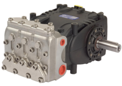
- For the Pratissoli KF30 pump (106 L/min at 200 bar, 40 kW), a plant running at only 60 L/min average flow and 120 bar average pressure is over-specified by approximately 40% in flow and 40% in pressure rating
Theoretical power (kW) = (Flow in L/min × Pressure in bar) ÷ 600
If a system theoretically requires 8 kW but the installed pump is rated at 40 kW, the equipment is over-sized by 80%. This creates two failure pathways:
1. Throttling inefficiency: Excess flow is bypassed through relief valves, converting energy to heat (typically 10–15°C temperature rise per relief valve activation)
2. Starved pump operation: Reduced load causes cavitation micro-bubbles at the pump inlet, leading to seal erosion and bearing wear
Step 3: Pressure Relief Bypass Analysis
Monitor relief valve discharge flow and temperature. If relief valves bypass more than 20% of pump discharge during normal operation, the pump is severely over-specified. Install temporary pressure gauges at pump discharge and actuator/circuit inlet to identify pressure drop caused by unnecessary relief valve opening.
Power Consumption Audit
Over-specified centrifugal and gear pumps consume disproportionate electrical power even at part-load. Compare actual kilowatt-hours consumed against nameplate rating multiplied by operating hours:
- Nameplate power ÷ actual measured power = utilization efficiency ratio
- Ratios below 0.60 (60%) indicate over-specification
- Cross-reference with motor amperage: measure actual current draw and compare to motor full-load amps (FLA) rating
For example, a motor rated 40 kW (typical for KF30 pumps) should draw approximately 75–80 amps at full load. If actual draw is 30–40 amps consistently, the pump is cycling at 40–50% capacity and is over-specified for the duty.
Diagnostic Section 2: Identifying Under-Specification and Demand Excursions
Peak Load Documentation
Under-specification is often overlooked because equipment functions during normal conditions but fails during transient peak demands. Document actual demand over at least two seasonal cycles (minimum 6 months in tropical regions, accounting for higher cooling loads in hot seasons).
Pressure Spikes and Flow Starvation
If discharge pressure exceeds rated specification by more than 10–15 bar during operation, the system is under-specified or the pump is operating against excessive back-pressure:
- Monitor pressure continuously during all operational phases
- Log instances when discharge pressure exceeds 90% of rated maximum (e.g., >180 bar for a 200 bar pump)
- Correlate pressure spikes with circuit load or ambient temperature changes
For high-pressure applications using Pratissoli SN7045 L pumps (45 L/min, 210 bar), sustained operation above 200 bar indicates either incorrect valve settings or demand exceeding the system design. This triggers:
1. Accelerated seal wear (mechanical seals fail 50% faster under sustained over-pressure)
2. Thermal stress: pressure exceeding rating by 10 bar can increase fluid temperature by 5–10°C
3. Cavitation risk on the pump inlet when the system throttles back during peak demand
Temperature Rise Analysis
Measure hydraulic or compressed air fluid temperature at pump discharge and return line:
- Normal operating temperature rise: 5–10°C (inlet to discharge)
- Sustained rise exceeding 15°C indicates the pump is working harder than design capacity
- Temperature exceeding 60°C (for hydraulic systems) or 50°C (for compressed air) signals either under-specification or insufficient cooling capacity
In humid Southeast Asian climates, inadequate cooling exacerbates thermal stress. If ambient temperature exceeds 35°C and system fluid reaches 65°C, the pump is under-sized relative to environmental conditions.
Flow Starvation Symptoms
Under-specified systems exhibit reduced flow under peak load:
- Actuators slow down or fail to move at rated speed during simultaneous operation
- Relief valve chatter (oscillation) occurs as the pump struggles to maintain pressure
- Cavitation noise (crackling or grinding) at the pump inlet during demand peaks
Use a temporary flow meter to verify actual discharge flow during peak operation. Compare to the pump nameplate rating:
- Actual flow ÷ rated flow = load utilization factor
- If factor exceeds 0.95 (95%) during peak demands, the pump is approaching maximum capacity and is under-specified for peak load
Diagnostic Section 3: Specification Mismatch in Hazardous Environments and Special Applications
ATEX and Compliance-Driven Over-Specification
In hazardous-area applications common in Southeast Asia's petrochemical and refining sectors, ATEX-compliant equipment (such as Interpump PUMP W2035 L ATEX, 35 L/min at 200 bar, 13.23 kW) carries premium pricing and inherent specification constraints. Plant managers often over-specify to "future-proof" installations or to match regulatory committee recommendations.
Diagnosis approach:
1. Review the original hazard area classification: Is the current Zone/Category classification still valid, or has facility mapping changed?
2. Verify actual duty cycle: ATEX equipment may be rated conservatively; actual demand may be 30–50% of specification
3. Assess compliance vs. efficiency trade-off: ATEX certification adds cost and sometimes larger motor frames; verify whether reduced-capacity alternatives exist for your Zone classification
HVAC and Condensate System Mismatches
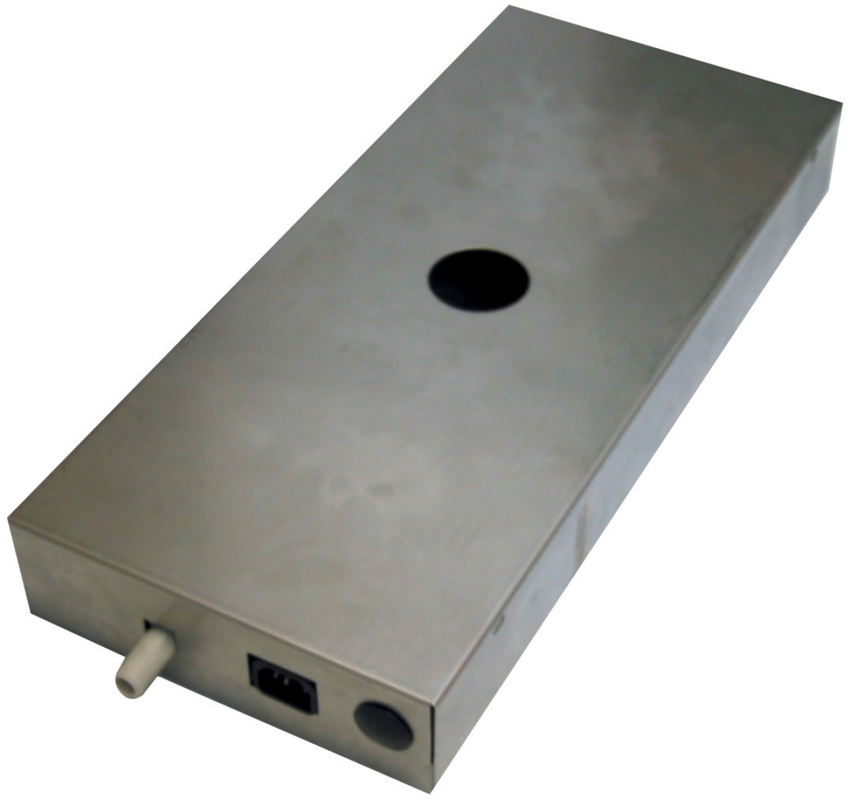
In tropical climates, condensate pump sizing is frequently over-specified due to worst-case humidity assumptions. The Clima Concept Display pump 5 liters (110 L/hr, 30 m head) is often installed when actual continuous condensate discharge averages 40–60 L/hr.
Diagnosis for HVAC systems:
- Measure actual condensate generation during high-humidity seasons (May–September in most Southeast Asian regions)
- Compare to pump discharge capacity; if the pump cycles less than 10 minutes per 24-hour period, it is over-specified
- Over-sized condensate pumps in humid climates cause stagnant water in oversized reservoirs, promoting bacterial growth and biofouling that restricts flow
Diagnostic Section 4: Root Cause Analysis and Corrective Actions
Specification Verification Checklist
For over-specified systems:
- Calculate actual duty cycle demand using measured pressure, flow, and duty cycle
- Evaluate downsizing to the next standard pump size (e.g., from 40 kW to 18.4 kW as available in Pratissoli SN7045 L) if demand is consistently 40–60% of current rating
- If downsizing increases peak pressure above rated specification, consider parallel pumps or variable displacement alternatives
- Recalibrate relief valve settings to actual system pressure requirement (typically 10% above maximum circuit load)
- Implement load-proportional control: variable displacement pumps or pump stop/start logic to eliminate throttling losses
- Upgrade to higher-displacement pump if peak demand consistently approaches 90%+ of rated capacity
- Implement flow staging: add a secondary pump to handle peak demands while the primary pump handles base load (improves part-load efficiency)
- If upgrading is not feasible, install an accumulator (hydraulic systems) to store energy during low-demand periods and discharge during peak demands, reducing peak pressure and flow requirements
- Verify cooling system capacity; in tropical regions, add supplemental heat exchangers if fluid temperature exceeds design limits
- Check system filtration; contaminant-fouled filters increase back-pressure and reduce pump efficiency by 5–10%, effectively under-sizing the pump
Alignment with Southeast Asian Operating Conditions
Tropical and equatorial environments introduce specific capacity challenges:
1. Seasonal demand variation: Cooling system loads in Malaysia, Indonesia, and Thailand spike 30–50% during peak summer months (April–September); initial commissioning in off-season often underestimates true demand
2. Ambient temperature effects: High ambient (35–38°C) reduces pump efficiency 2–3% per degree Celsius above design baseline; systems sized for 25°C ambient under-perform at 35°C
3. Humidity and seal degradation: High moisture promotes corrosion inside pump casings and accelerates mechanical seal failure; over-specified systems circulate fluid less frequently, allowing moisture to settle and concentrate
4. Power grid instability: Voltage sag and frequency variation (common in developing regions) reduce motor torque output by 3–5%; undersized pumps cannot overcome this deficit
Implementation Timeline
- Week 1–2: Install instrumentation (pressure gauges, flow meters, temperature sensors) on pump inlet, discharge, and return lines
- Week 3–8: Collect baseline data across minimum two complete operational cycles (night/day, peak/off-peak, seasonal variation if possible)
- Week 9–10: Analyze data using power calculation formulas and pressure-flow curves; identify mismatch magnitude
- Week 11–12: Develop retrofit or replacement specification; obtain quotes from industrial equipment suppliers like 3G Electric for alternative pump models (e.g., downsizing from KF30 to SN7045 if appropriate)
- Month 4+: Execute corrective action during planned maintenance window
Practical Example: Capacity Mismatch in a Singapore Manufacturing Facility
A semiconductor assembly plant commissioned a 40 kW hydraulic system (similar specification to KF30) for a new test fixture requiring 60 L/min at 120 bar. After 8 months of operation, plant managers observed:
- Motor amperage: 32 amps (vs. nameplate FLA of 75 amps)
- Discharge pressure oscillated between 95–135 bar (relief valve cycling)
- System fluid temperature: 58°C (acceptable but at upper threshold)
- Monthly electricity consumption: 9,200 kWh
Root cause: Equipment was sized for future expansion that never materialized; procurement selected a standard platform pump without detailed demand engineering.
Solution: Retrofit with a 20 kW variable displacement pump (half the original power rating) and implement load-sensing control. Result: electricity consumption reduced to 5,400 kWh/month (41% savings), system fluid temperature dropped to 48°C, and pump service life extended by estimated 50% due to reduced thermal stress.
Cost-benefit: Equipment retrofit cost SGD 18,000; annual electricity savings SGD 14,400; payback period 15 months with added reliability gains.
---
Summary: Actionable Steps for Plant Managers
1. Measure, don't estimate: Install permanent or temporary instrumentation to document actual pump discharge pressure, flow rate, and power consumption across the complete duty cycle
2. Compare to specification: Calculate actual power demand using the formula (Flow × Pressure) ÷ 600; compare to nameplate kW rating
3. Identify mismatch type: Over-specification (efficiency loss, energy waste) or under-specification (reliability risk, thermal stress)
4. Correlate with symptoms: Pressure relief cycling, temperature rise, flow starvation, or cavitation noise confirm the diagnosis
5. Develop retrofit or replacement strategy: Work with industrial equipment suppliers like 3G Electric to evaluate downsizing, variable displacement conversion, or parallel pump configurations
6. Account for climate factors: Southeast Asian tropical conditions amplify capacity mismatches; size for peak ambient temperature (35–38°C) and peak seasonal demand, not average conditions
3G Electric's distribution network across Southeast Asia has supported thousands of plant retrofits. Contact your local 3G Electric representative with measured system data to receive engineering-backed recommendations for pump selection and capacity optimization.