Understanding Pumps & Compressors Capacity Mismatch
Capacity mismatch represents one of the most overlooked yet costly failure modes in industrial Pumps & Compressors operations. Unlike sudden mechanical failures, capacity problems develop gradually, masking themselves as normal degradation until system performance collapses entirely. With over 35 years of experience distributing industrial equipment across the Asia-Pacific region, 3G Electric has observed that approximately 40% of performance complaints stem not from equipment defects, but from specification errors during procurement or operational changes that exceeded original design parameters.
Capacity mismatch occurs when the installed pump or compressor fails to deliver the flow rate, pressure, or combined displacement required by downstream processes. This can manifest in two opposing scenarios: undersized systems that cannot sustain peak demand, and oversized systems that operate inefficiently in part-load conditions, generating excessive heat and accelerating component wear.
The distinction between true equipment failure and capacity inadequacy is critical. An undersized pump delivering 85 L/min when the process demands 100 L/min appears to fail, but the pump itself functions correctly. Similarly, an oversized compressor running continuously at 40% load will eventually fatigue bearings and seals through prolonged low-efficiency operation. Understanding this difference determines whether the solution involves retrofit, replacement, or process redesign.
Diagnostic Framework: Load Profiling and Demand Analysis
Effective diagnosis begins with systematic load profiling—quantifying actual system demand across all operational states. This step separates genuine capacity problems from transient operating anomalies.
Step 1: Establish Baseline Demand Requirements
Document the theoretical demand for all connected consumers. For industrial pump systems, this includes:
- Primary load (main process actuators, cylinders, or flow applications)
- Secondary loads (auxiliary circuits, cooling systems, pilot pressure)
- Peak simultaneous demand versus sequential demand patterns
- Duty cycle—percentage of time each load operates
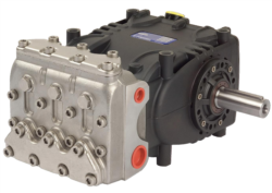
For example, a hydraulic press circuit with a main pump delivering 106 L/min at 200 bar (such as the Pratissoli KF30) may be specified for continuous 80% utilization, but field experience reveals peak demand occurs only 15% of the time. The remaining 85% operates at reduced load, creating oversizing conditions.
Step 2: Field Flow Rate Measurement
Deploy calibrated flow meters to measure actual discharge across all operating conditions:
- Use digital turbine meters for general hydraulic systems (accuracy ±2%)
- Install temporary magnetic meters on discharge lines for 7-14 day monitoring windows
- Record flow at 25%, 50%, 75%, and 100% process load states
- Compare measured flows against pump nameplate specifications
A Pratissoli SN7045 L pump rated for 45 L/min at 1450 rpm should verify nameplate performance; deviations exceeding ±5% indicate throttling, internal leakage, or mechanical degradation requiring separate diagnosis.
Step 3: Pressure Mapping Under Load
Measure system pressure at pump discharge, main relief setting, and downstream circuit pressure drops:
- Inadequate pressure to reach process target pressure (especially above relief setting) indicates undersizing
- Excessive pressure drop across process circuits suggests undersized conductors or excessive throttling
- Relief opening at lower-than-set pressure may indicate internal pump leakage masking as capacity loss
Install pressure transducers at three points: pump outlet, main circuit inlet, and final actuator inlet. For high-pressure applications like the Interpump W2035 L ATEX rated 200 bar with ATEX hazardous area certification, verify relief setting matches process requirements within ±5 bar tolerance.
Undersized System Diagnosis and Remediation
Undersized Pumps & Compressors systems exhibit consistent, measurable indicators that distinguish them from worn equipment.
Diagnostic Indicators
Inability to sustain rated pressure under full load: The pump reaches maximum displacement but pressure fails to reach process set-point. Flow vs. pressure curves flatten, indicating the pump operates at maximum volume but cannot maintain pressure against system demand.
Extended cycle times: Process actuators move more slowly than design specification. A hydraulic cylinder specified for 8-second extension may drift to 12-15 seconds as undersizing forces throttling to regulate pressure.
Relief valve opening prematurely: If system pressure continuously approaches relief set-point without reaching it, the pump cannot supply sufficient flow at design pressure. Premature relief cracking (opening 10-15 bar below set-point) indicates internal pump leakage, but consistent pressure shortfalls of 20+ bar suggest undersizing.
Cumulative demand exceeding installed capacity: Process modifications—additional workstations, increased production rates, or auxiliary system additions—can increase demand beyond original specification. Document changes to the system over its operational lifetime.
Remediation Strategies
Upgrade to larger displacement: The most direct solution involves installing a pump with higher flow capacity. For industrial applications requiring 100+ L/min at 200 bar, the Pratissoli KF30 delivering 106 L/min at 40 kW represents a common upgrade path from smaller units. This requires motor power verification and circuit redesign to handle increased flow velocities.
Add parallel pump capacity: Install a secondary pump operating in parallel during peak demand periods. Variable displacement pumps with load-sensing controls can activate standby capacity only when primary pump load exceeds 80% displacement. This approach preserves efficiency during normal operation while providing peak capacity.
Implement demand-side efficiency: Before expanding supply, optimize consumption through:
- Circuit component upsizing (larger bore cylinders, faster actuators)
- Process flow prioritization (staged operation sequence to reduce simultaneous demand)
- Pressure reduction where feasible (lower circuit pressure reduces pump workload)
Oversized System Diagnosis and Remediation
Oversized Pumps & Compressors systems present a paradox: they supply adequate capacity but operate inefficiently, generating heat and accelerating seal and bearing degradation.
Diagnostic Indicators
Continuous relief valve bleed-off: Oversized pumps reach system pressure quickly, then excess flow is dumped across the relief valve continuously. This generates heat load proportional to excess flow: Heat (kW) = (Excess Flow in L/min × Pressure in bar) / 600. A 200 L/min pump feeding a 80 L/min process at 200 bar generates 40 kW of unwanted heat energy.
Elevated fluid temperature during partial load operation: Undersized systems overheat during peak demand due to high pressure and throttling. Oversized systems overheat during normal partial-load operation due to continuous relief bleed. Fluid temperature exceeding 60°C during 50% load operation (when design temperature is 45°C at full load) indicates oversizing.
Excessive duty cycle on pressure control components: Load-sensing proportional valves in oversized systems must continuously throttle to regulate pressure, reducing valve spool life from 5-7 years to 2-3 years. Proportional valve pilot failures occur 2-3x more frequently in oversized systems.
Bearing and seal wear pattern acceleration: High-speed operation (rpm) combined with continuous relief bleed produces vibration and thermal stress, reducing bearing life and mechanical seal durability despite operating at rated pressure.
Energy waste quantification: Calculate excess power loss: Wasted Power (kW) = (Installed Capacity L/min − Actual Demand L/min) × System Pressure (bar) / 600. An oversized compressor delivering 500 m³/hr when demand is 300 m³/hr at 8 bar pressure wastes approximately 26.7 kW continuously—equivalent to $4,800-6,200 USD annually in electricity costs for Singapore's industrial rates.
Remediation Strategies
Install load-sensing pressure compensators: Replace fixed-displacement pumps with load-sensing variable displacement units. The pump output automatically adjusts to match demand flow at a constant margin above process pressure (typically 20 bar). This eliminates relief valve bleed and reduces wasted energy by 30-40%.
For systems currently using fixed pumps like the Pratissoli SN7045 L (45 L/min, fixed displacement), migrating to load-sensing variants reduces standby losses during low-demand periods.
Implement demand-proportional unloading: Configure pump discharge to tank bypass during idle periods, or use proportional directional control valves with electronic load sensing. Modern proportional valve systems reduce underslung pressure to 5-10 bar during no-load conditions.
Downsize to matched capacity: If process demand consistently operates at 60-70% of installed pump capacity and load-sensing upgrades are economically unfeasible, specify a smaller pump matching actual demand. For applications requiring precise 50 L/min delivery, the Interpump W2035 L ATEX (35 L/min) may be undersized, but parallel operation with the WW90 L (8 L/min) provides staged capacity matching.
Performance Verification After Optimization: Monitor discharge temperature and pressure during typical production cycles. Relief valve bleed-off should reduce by 50-70%. System temperature at 75% load should match or be lower than pre-optimization temperatures at equivalent load states.
Field Diagnostics: Load Testing Protocol
Systematic load testing quantifies capacity adequacy with precision.
Test Setup
1. Install analog or digital gauges on pump discharge and main circuit inlet
2. Place calibrated flow meter on pump discharge line (turbine or electromagnetic type)
3. Connect temperature probe to pump discharge fluid (ideally integrated into return line filter)
4. Verify all process loads operational and stable before commencing test
5. Record baseline data for 30 minutes at current operating load
Test Sequence
Phase 1: No-Load Baseline (5 minutes)
- Record pump discharge pressure with no actuators energized
- Undersized systems: discharge pressure will be near zero
- Oversized systems: discharge pressure will approach relief set-point (pump unloaded at idle)
- Note fluid temperature
- Progressively enable process loads to reach 25%, 50%, 75% of maximum simultaneous demand
- Hold each stage for 10 minutes, recording flow, pressure, and temperature
- Evaluate pressure stability (±10 bar is acceptable)
- Measure flow rate—should increase proportionally with load
- Enable all primary and secondary loads simultaneously
- Record flow, pressure, and temperature
- Compare discharge flow to pump nameplate—if 15%+ below spec, investigate internal leakage
- Verify system pressure reaches process target pressure
- Operate at typical production duty cycle (mix of full, partial, and idle states)
- Continuous temperature monitoring—should stabilize within ±3°C by hour 2
- Relief valve actuation frequency: excessive opening (>5 times per minute) indicates oversizing
- Log fluid temperature each hour—maximum should not exceed design limit (typically 60°C)
Compare measured results against original equipment specification:
- Flow variance >±8%: Indicates internal pump leakage or worn displacement components (separate diagnostic pathway)
- Pressure variance >±15% at equivalent load: Indicates relief setting drift or internal leakage
- Temperature rise >20°C during test: Indicates energy inefficiency (oversizing or excessive throttling)
- Relief valve continuous opening: Definitive indicator of oversizing if process demand <80% pump displacement
Practical Applications and Equipment Selection
Capacity matching begins at procurement. Working with 3G Electric's 35+ years of industrial distribution experience, specify pumps with flexibility for future demand growth without excessive oversizing.
For high-pressure hazardous area applications demanding ATEX compliance, the Interpump W2035 L ATEX delivers 35 L/min at 200 bar with certified compliance. Its compact 13.23 kW power requirement allows integration into constrained electrical infrastructure while providing adequate capacity for moderate-demand circuits.
For general industrial hydraulic systems, the Pratissoli KF30 (106 L/min, 200 bar, 40 kW) suits applications requiring sustained flow with 20-25% capacity margin for growth. Load-sensing controls maintain efficiency during partial-load operation.
For smaller auxiliary circuits and pilot pressure systems, the Interpump WW90 L (90 bar, 8 L/min, 1.47 kW) integrates valve functionality with compact footprint, eliminating external valve requirements and reducing connection points.
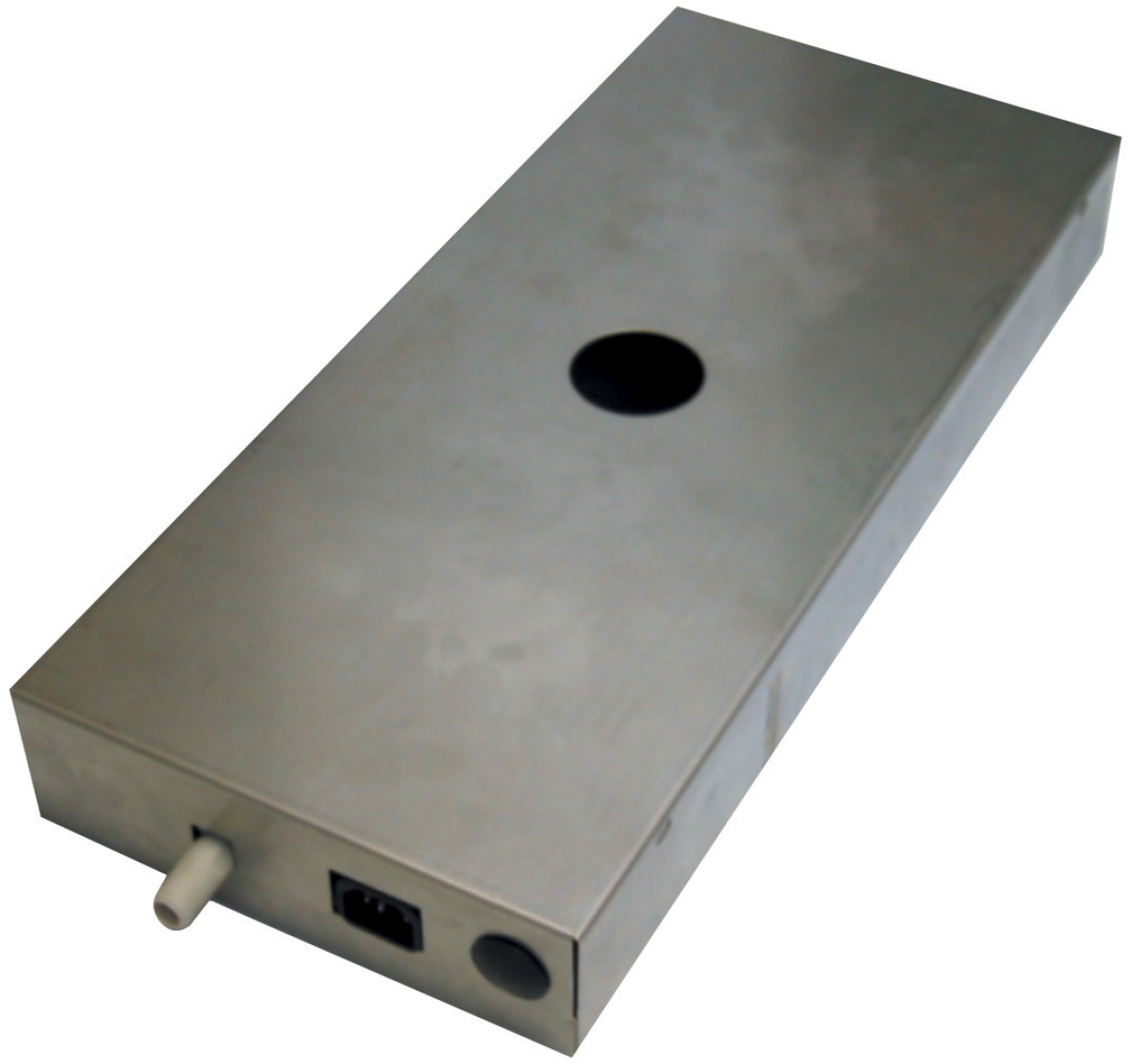
For HVAC condensate systems operating in Singapore's humid tropical climate, precise capacity matching is critical. The Clima Concept Display pump 5 liters (110 L/hr, 30m head) matches condensate generation rates in residential and light commercial cooling systems, preventing tank overflow during peak humidity periods.
Specification Validation: Before finalizing procurement, conduct load analysis documenting peak, average, and idle demand across a full annual cycle. Specify pump capacity at 85-90% of simultaneous peak demand (avoiding oversizing) with pressure margin of 10-15% above highest individual circuit pressure requirement.
Conclusion
Capacity mismatch diagnosis requires systematic load profiling, field measurement, and comparative analysis against design specifications. Undersized systems manifest as pressure or flow inadequacy; oversized systems as thermal inefficiency and accelerated component wear. Both scenarios demand corrective action—undersizing through capacity expansion or process optimization, oversizing through load-sensing upgrades or downsizing.
Regular diagnostic testing—conducted quarterly for critical systems—prevents capacity mismatch from escalating into catastrophic failure. With precise field data and proven remediation strategies, industrial professionals can optimize Pumps & Compressors performance, reduce energy consumption, and extend equipment service life across Singapore's demanding industrial operations.