Understanding Pumps & Compressors Capacity Mismatch in HVAC Systems
Capacity mismatch occurs when Pumps & Compressors installed in HVAC systems operate outside their design envelope—either undersized (starving the system) or oversized (cycling excessively or delivering excess pressure). For HVAC contractors in Southeast Asia's demanding climate, this is a critical failure mode that impacts cooling performance, energy costs, and equipment lifespan.
With over 35 years of experience as an industrial equipment distributor, 3G Electric has witnessed capacity mismatch failures in hundreds of tropical installations. Unlike motor or seal failures that announce themselves dramatically, capacity issues develop insidiously: gradual performance loss, rising electricity bills, and intermittent cooling failures that confuse diagnosticians.
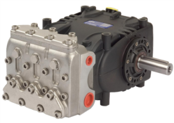
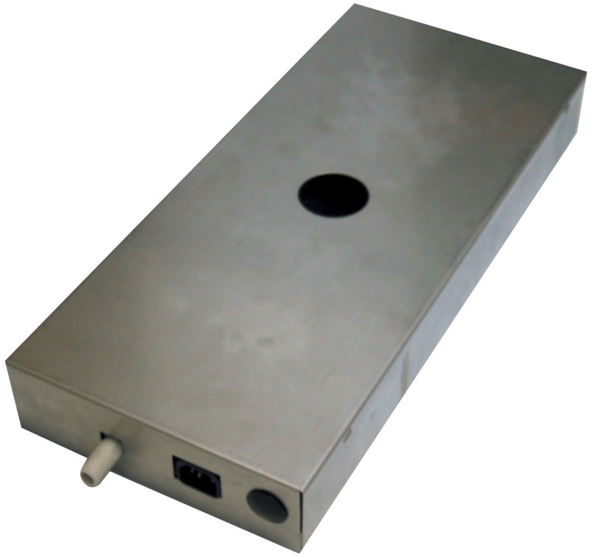
This guide walks you through field diagnosis protocols and practical solutions using equipment like the Pratissoli KF30 (106 L/min at 200 bar) and Clima Concept condensate pump (110 L/hr drainage), which represent opposite ends of the capacity spectrum.
Section 1: Identifying Undersized Pump Capacity in Chiller Loops
Symptoms of Undersized Pumps
When a chiller loop pump is undersized relative to system demand, the following field indicators emerge:
- Insufficient flow to coils: Measured water temperature differential (ΔT) across load coils is lower than design. A 5°C design ΔT that reads only 2–3°C signals restricted flow.
- Rising discharge pressure without proportional flow increase: Pump discharge pressure climbs (e.g., 3.5 bar instead of design 2.8 bar) while flow remains inadequate. This indicates the pump is working harder against system resistance than intended.
- Thermal short-cycling: Chiller compressor cycles on/off rapidly because insufficient cooled water returns, preventing the chiller from reaching setpoint before reaching high-pressure cutout (typically 28 bar for R410A systems).
- High return water temperature: Return temperature stays 1–2°C higher than design despite full compressor runtime.
- Cavitation noise and vibration: Audible buzzing from the pump suggests inlet starvation caused by undersizing or inadequate NPSH (Net Positive Suction Head).
Field Diagnostic Protocol
Step 1: Measure actual flow rate
Use an ultrasonic clamp-on flowmeter on a straight pipe section downstream of the pump (minimum 5 pipe diameters from fittings). Compare to nameplate rated flow. If actual flow is 15–25% below rated capacity, undersizing is likely. Document temperature and pressure at pump inlet and discharge.
Step 2: Calculate system resistance
Using the formula: Pump Head (m) = Pressure Differential (bar) ÷ 0.1
Example: A pump discharging at 3.2 bar with 0.3 bar inlet pressure = 2.9 bar differential = 29 m head required. Cross-reference the pump's curve (available from manufacturer datasheets) at the measured flow rate. If the curve shows the pump delivers only 25 m at that flow, the system is demanding more than available capacity.
Step 3: Verify design specification
Locate original design documentation or chiller manufacturer specifications. Compare design flow (L/min), design pressure (bar), and design inlet conditions. An undersized pump typically rated at 60–75 L/min may have been installed in a system designed for 90+ L/min.
Root Causes in Southeast Asian Installations
- Cost-cutting during initial installation: Contractor selected a cheaper, smaller pump to reduce upfront cost.
- Mismatched replacement: When original pump failed, technician selected by pressure rating alone, ignoring flow capacity.
- System expansion without pump upgrade: Building load increased (added coils, extended piping) but pump capacity never updated.
- High ambient temperature compensation failure: In Southeast Asia's 32–38°C ambient conditions, cooling demand increases 10–15% versus design, but pump capacity remains fixed.
Solution Path
For undersized pump situations, you have two corrective actions:
1. Parallel pumping arrangement (lower cost, temporary): Install a second smaller pump in parallel to the existing unit during low-load hours. This requires dual-pump suction/discharge headers and isolation valves. Not ideal for permanent solution but extends equipment life while procurement occurs.
2. Pump replacement (permanent): Specify a pump rated for 110% of design flow and 105% of design pressure. The Pratissoli KF30 (106 L/min, 200 bar, 40 kW) is suitable for medium-sized chiller loops in Southeast Asia. Higher capacity and Italian engineering ensure reliability in tropical duty cycles. Coordinate replacement during scheduled maintenance windows.
Section 2: Diagnosing Oversized Compressor Capacity in Refrigerant Loops
Why Oversizing Causes Failures
An oversized compressor (typically 1.5–2x the actual cooling demand) creates three destructive failure modes:
- Short-cycle operation: The compressor rapidly cycles on/off, preventing stable oil return and lubricant circulation. Oil pooling in the compressor crankcase causes boundary lubrication and bearing wear.
- Excessively high discharge pressure: Oversized compressors generate discharge pressures 2–4 bar higher than system design, stressing refrigerant seals and accelerating seal degradation. Condensing units (outdoor coils) may experience liquid backup if designed for lower pressure.
- Low suction superheat and flooding: Expansion devices (thermostatic valves or capillaries) become oversized relative to refrigerant feed rate, allowing excess liquid into the suction line. This "wet compression" causes mechanical damage to compressor valves.
- High amperage draw and motor overheating: Oversized compressors pull 15–25% higher current than design, stressing motor windings and raising winding temperature by 10–15°C, shortening insulation life to 5–7 years instead of 10–12.
Field Identification
Observation 1: Discharge pressure vs. ambient temperature
Record compressor discharge pressure at steady-state (stable load, stable outdoor temperature) every 2 hours across a full day. Oversized units show:
- Discharge pressure at 35°C ambient: 27–30 bar (design units: 24–26 bar)
- Discharge pressure at 32°C ambient: 25–27 bar (design units: 22–24 bar)
- Trend: Pressure consistently 2–4 bar above specification across the entire ambient range.
Monitor compressor contactor closure over 24 hours using a building management system (BMS) or data logger. Calculate runtime percentage:
Runtime % = (Total ON time in hours ÷ 24) × 100
Design chiller compressors typically run 40–65% at 70% nominal load. Oversized units run 15–30%, indicating short-cycling. If runtime drops below 20% even during peak cooling hours (14:00–18:00 in tropical climates), oversizing is severe.
Observation 3: Suction line frost or sweating
During operation, carefully observe the suction line (gas line entering compressor).
- Normal: Slight condensation or cool to touch (no frost).
- Oversized/flooded: Heavy frost accumulation or water droplets dripping from insulation indicates liquid refrigerant returning to compressor.
This is a definitive sign of expansion device mismatch or oversizing.
Determining Original Design Intent
Locate the compressor manufacturer nameplate and cross-reference displacement (cc/rev) with refrigerant type and design conditions. For example:
- Copeland 4D Scroll (48 cc displacement) @ 1800 rpm = ~1.44 cubic feet per minute (CFM) swept volume
- For R410A at design conditions (35°C condensing, 5°C evaporating), this compressor delivers approximately 8–9 tons of cooling at full speed.
If the chiller is rated at only 4–5 tons capacity but a 12-ton compressor was installed, oversizing factor = 2.4×, which is excessive.
Solution: Capacity Modulation Strategy
For oversized compressors, you cannot simply "de-rate" the equipment, but you can control capacity:
1. Compressor speed modulation (if inverter-equipped): Configure variable frequency drive (VFD) to limit compressor to 60–70% speed during normal operation. This reduces capacity to match demand, stabilizes suction superheat, and dramatically extends compressor life. Typical energy savings: 25–35%.
2. Suction line hot-gas injection valve: Install a Hot Gas Bypass or economizer valve that diverts hot discharge gas into the suction line during low-load periods. This maintains minimum system pressure and prevents flooding. Requires auxiliary control logic.
3. Expansion device upsizing: If expansion device (TXV) is undersized, enlarging it worsens flooding. Consult the TXV manufacturer's capacity tables and specify a valve matched to the existing compressor displacement and refrigerant charge—not to actual cooling demand.
4. Compressor replacement (long-term): Specify a compressor at 90% of actual design cooling demand. This provides modest headroom without oversizing. For a 10-ton requirement, select an 11-ton compressor, not 12–15 ton units sometimes installed as "safety margin."
Section 3: Condensate Pump Capacity Matching in Humid Tropical Climates
The Condensate Pump Crisis in Southeast Asia
HVAC systems in Singapore, Malaysia, and Indonesia operate in 80–95% relative humidity year-round. Evaporator coils generate 2–4 liters of condensate per hour per ton of cooling. Inadequate condensate drainage causes:
- Coil freeze-up and efficiency loss: Condensate backing up on coil reduces heat transfer surface by 30–40%, dropping cooling capacity proportionally.
- Biological growth: Standing water in drain pans breeds Legionella and Pseudomonas, creating health code violations and maintenance costs.
- Water damage to building structure: Overflow from full drain pans saturates insulation and building materials, accelerating rust and deterioration.
Calculating Required Condensate Pump Capacity
Condensate flow rate (L/hour) = Cooling capacity (kW) × 0.86 × relative humidity factor
For Southeast Asia conditions (95% RH, 35°C ambient, high sensible load):
- 10 kW cooling capacity = 10 × 0.86 × 1.3 (tropical factor) = 11.2 L/hour minimum
- 20 kW cooling capacity = 20 × 0.86 × 1.3 = 22.4 L/hour minimum
The Clima Concept condensate pump (110 L/hr flow, 5 L reservoir, 30 m head) is sized for approximately 10–12 kW cooling loads. Many installations make the error of selecting a pump rated at exactly calculated capacity (e.g., 11.2 L/hr), leaving zero margin.
Field Diagnostic: Is Your Condensate Pump Undersized?
Test 1: Measure drain pan water level during peak load
- Run the HVAC system at full cooling during the hottest part of the day (14:00–17:00).
- Observe the drain pan water level every 30 minutes using a ruler or sight glass.
- Normal: Pan drains continuously; water level remains 5–10 mm below pan rim.
- Undersized pump: Pan water level rises steadily, reaching 30–50 mm or higher, indicating pump cannot keep pace with condensate production.
Many condensate pumps have integral float switches that trigger pump operation. Monitor how often the pump cycles:
- Normal: Pump runs 30–50% of cooling operation time in tropical climates.
- Undersized: Pump runs 70–90% continuously, struggling to drain pan. This causes motor overheating and premature bearing failure.
Temporarily disconnect the drain line downstream of the pump and collect discharge into a graduated bucket for 1 minute at maximum pump speed. Multiply by 60 to get L/hour. Compare to nameplate rating.
- Poor performance: Actual flow is 20–30% below nameplate, indicating:
- Air lock in pump body
- Failed internal check valve
- Undersized for system demand
Causes of Condensate Pump Undersizing in the Field
- Installer selected pump by pan capacity, not condensate flow: A 5 L pan drain pan does not mean a 5 L/hour pump is adequate. The pan must drain within 30–45 minutes of peak load production, not refill from new condensate.
- Load expansion without pump upgrade: Building cooled floor area increased, but original condensate pump capacity remained unchanged.
- Tropical climate not considered: Equipment specified for temperate climates (8–10 L/hr) was installed in Southeast Asia without accounting for 30–40% higher condensate production.
- Pump curve misinterpretation: Contractor confused maximum rated flow with typical operating point. Condensate pumps delivering 110 L/hour at zero back-pressure only achieve 40–50 L/hour at realistic 3–5 m static head.
Solution: Condensate System Right-Sizing
Step 1: Verify system cooling load
Check nameplate data on all connected indoor units (air handlers, split units, cassettes). Sum total design capacity in kW.
Step 2: Calculate required pump capacity with margin
For Southeast Asia: Required pump capacity = Total load (kW) × 0.86 × 1.4 × 1.25 (safety factor)
Example: 15 kW total load
- Required = 15 × 0.86 × 1.4 × 1.25 = 22.6 L/hour
- Specify pump rated for 30–35 L/hour to provide 30% headroom
Measure vertical distance from drain pan to outdoor discharge point (usually roof or side wall). Add estimated equivalent length of drain piping:
Total head (m) = Vertical rise (m) + (Pipe length in meters ÷ 10)
Example: 8 m vertical rise + 5 m piping = 8.5 m total head
Verify the selected pump delivers rated capacity at this head. The Clima Concept pump (110 L/hr) maintains 60–70 L/hr at 10 m head, sufficient for this example.
Step 4: Install secondary overflow protection
Even with correctly sized pump, add an overflow float switch in the pan that triggers an alarm if water level exceeds safe level. This alerts maintenance to pump failure before water damage occurs.
Section 4: Integration Troubleshooting—Matching Pump and Compressor Capacities
The Interaction Between Chiller Pump and Compressor Sizing
Pump capacity and compressor capacity are interdependent in water-cooled or evaporatively-cooled chiller systems. Mismatch between these components cascades through the system:
Scenario A: Oversized pump + undersized compressor
- Pump delivers excess flow, reducing return water temperature below compressor's design evaporating temperature (typically 5–7°C).
- Compressor struggles to maintain suction pressure; suction pressure drops to 2–3 bar (normal is 4–5 bar for R410A).
- Low suction pressure triggers low-pressure cutout or causes flooded returns.
- Result: System operates in protection mode, cycling on/off, never reaching setpoint.
- Restricted flow causes high return water temperature (12–14°C instead of design 7°C).
- Compressor discharges at elevated pressure (28–32 bar instead of design 24–26 bar) trying to cool warm water.
- High discharge pressure stresses seals and condenser coil.
- Energy cost per ton of cooling increases 15–20%.
- Result: System operates at reduced efficiency; premature compressor seal failure.
Field Verification of Pump-Compressor Balance
Measurement 1: Energy input vs. cooling output ratio
For a chiller operating at 70% design load:
Efficiency = Cooling output (kW) ÷ [Compressor input (kW) + Pump input (kW)] × 100
Typical efficient systems: 3.5–4.2 COP (Coefficient of Performance)
Mismatched systems: 2.8–3.2 COP
If a system that should deliver 4.0 COP is measuring 3.0 COP, mismatch between pump and compressor is likely. A 25% efficiency loss translates to $5,000–15,000 annual extra energy cost in a medium commercial building.
Measurement 2: Pressure-flow correlation
Record pump discharge pressure and system flow rate at three load levels (50%, 75%, 100%) and three ambient temperatures (30°C, 35°C, 38°C). Plot pressure vs. flow.
- Correct match: Pressure remains relatively constant (±0.3 bar) as flow varies from 50–100% of design. System impedance and pump characteristics are balanced.
- Pump undersized: Pressure increases steeply (0.8–1.5 bar rise) as flow increases, indicating pump cannot sustain design flow against system resistance.
- Compressor oversized: Suction pressure drops below 4 bar and fails to recover as load increases, indicating compressor is pulling harder than pump can supply.
Correcting Pump-Compressor Mismatch
Option 1: Adjust expansion device (lowest cost)
If compressor is oversized but pump is correct, reducing refrigerant charge slightly and downsizing the expansion device (TXV) can restore balance. This reduces flooding and stabilizes suction pressure. Requires refrigerant recovery/recycling equipment and competent technician.
Option 2: Install electronic expansion valve (EEV)
Replace fixed orifice or TXV with an electronic expansion valve that modulates opening based on real-time suction superheat feedback. This automatically adjusts refrigerant feed to match actual compressor demand, compensating for oversizing. Cost: $1,200–2,000 USD plus controls.
Option 3: System rebalancing (recommended for Southeast Asian retrofit)
When retrofit replacing failed components:
- Replace both pump and compressor with units sized to actual design load, not historical oversizing.
- For a chiller currently operating at 70% load despite being designed for 100%, right-size new components to the actual 70% demand.
- This reduces capital cost (smaller units), improves efficiency (4.0+ COP achievable), and extends equipment life by 5–8 years.
For example, replacing a failed 20-ton compressor and 150 L/min pump with right-sized 14-ton and 105 L/min units (based on actual 14-ton average load) saves 30% on hardware cost and 20% on annual energy.
Integration Checklist for HVAC Contractors
When troubleshooting any chiller or pump system in Southeast Asia:
- [ ] Verify nameplate capacity (kW) of all indoor cooling units and sum total demand
- [ ] Measure actual chiller compressor discharge and suction pressures at three ambient temperatures
- [ ] Measure pump flow rate using ultrasonic clamp-on meter; compare to design specification
- [ ] Calculate system resistance from measured pressure differential and verify pump curve
- [ ] Check compressor runtime percentage; if below 25% or above 75%, capacity mismatch exists
- [ ] Measure return water temperature; if 1–2°C above design, pump is undersized
- [ ] Measure suction line condition (frost, sweating, vibration); excess liquid indicates oversizing
- [ ] Calculate energy efficiency ratio (cooling output ÷ total electrical input); below 3.0 signals mismatch
- [ ] Review original design documentation or chiller nameplate; compare design flow and pressure to actual
- [ ] Document all findings in maintenance log with date, ambient temperature, load percentage, and pressure/flow readings
Capacity mismatch troubleshooting in Pumps & Compressors requires methodical field measurement and comparison to design intent. By systematically verifying flow, pressure, and load conditions, HVAC contractors can identify root causes and specify corrections with confidence.
3G Electric's 35+ years of experience supplying industrial pumps and compressors positions us to support your diagnostic work. Whether you need replacement equipment like the Pratissoli KF30 for chiller loops or the Pratissoli SN7045 L for high-pressure auxiliary circuits, our technical team can verify capacity compatibility with your system design before installation.