Understanding Measurement & Detection System Failures
Measurement and Detection systems form the backbone of industrial facility monitoring, yet they remain among the most frequently misdiagnosed problems in maintenance workflows. When temperature readings fluctuate erratically, pressure indicators fail to respond, or electrical measurements become unreliable, maintenance teams often waste hours replacing perfectly functional equipment.
With over 35 years of experience as an global industrial equipment distributor, 3G Electric has observed that 70% of measurement system failures stem not from equipment malfunction, but from installation errors, calibration drift, or environmental contamination. By understanding the systematic causes of failure, your maintenance team can implement targeted diagnostics that pinpoint issues in minutes rather than days.
This troubleshooting guide focuses on the four most critical measurement and detection categories: thermometric systems, electrical measurement instruments, expansion tank monitoring, and integrated sensing networks. Each section provides step-by-step diagnostic procedures that maintenance teams can execute with minimal specialized training.
Section 1: Thermometric System Diagnostics and Calibration Verification
Common Thermometric Failures and Root Causes
Temperature measurement failures represent approximately 40% of all measurement system issues in industrial environments. These failures typically fall into three categories: sensor isolation problems, thermal mass mismatches, and calibration drift.
Sensor Isolation Problems occur when thermowells become fouled with deposits, scale, or process fluid residue. This creates an insulating barrier that delays temperature response and reduces reading accuracy. Additionally, poor thermal contact between the sensor and the thermowell wall prevents accurate heat transfer, resulting in lag times exceeding 30 seconds on systems that should respond within 5 seconds.
Thermal Mass Mismatches happen when liquid-filled thermometers like the CBM Axial thermometer D65 -40/+40°C L5cm with thermowell are installed in applications where rapid temperature changes occur. The bulb's thermal mass causes the liquid to respond slower than the actual process temperature, creating systematic undershooting or overshooting during transient conditions.
Calibration Drift develops gradually over 12-24 months as internal components settle and fluid properties change. Industrial thermometers can drift 2-3°C across their operating range without showing external signs of failure.
Thermometric Troubleshooting Procedure
Step 1: Verify Installation Compliance
- Confirm the thermometer is installed at the correct immersion depth (typically 1/3 to 1/2 of pipe diameter)
- Check that the thermowell is installed perpendicular to flow direction (not parallel)
- Ensure the thermowell opening faces slightly downstream (30-45° angle)
- Verify the sensor is centered in the thermowell, not touching the walls
- Record the current temperature reading
- Initiate a controlled temperature change (hot water test or process adjustment)
- Time how long the thermometer takes to stabilize at the new temperature
- For industrial applications, response time should be 30-90 seconds depending on thermowell material
- If response time exceeds 2 minutes, suspect thermowell fouling
- Use a portable reference thermometer at the same location
- Compare readings across the operating range (bottom 10%, middle 50%, top 10% of scale)
- Readings should match within ±1-2% of the sensor's rated accuracy
- If differences exceed 2%, the sensor requires recalibration or replacement
- For non-pressurized systems: Remove thermowell and soak in appropriate solvent (white vinegar for mineral deposits, isopropyl alcohol for organic residue)
- Use soft brass or plastic brushes (never stainless steel) to avoid scratching the internal surface
- Flush thoroughly with distilled water and allow complete air drying
- Reinstall using high-temperature thermally conductive paste to improve sensor contact
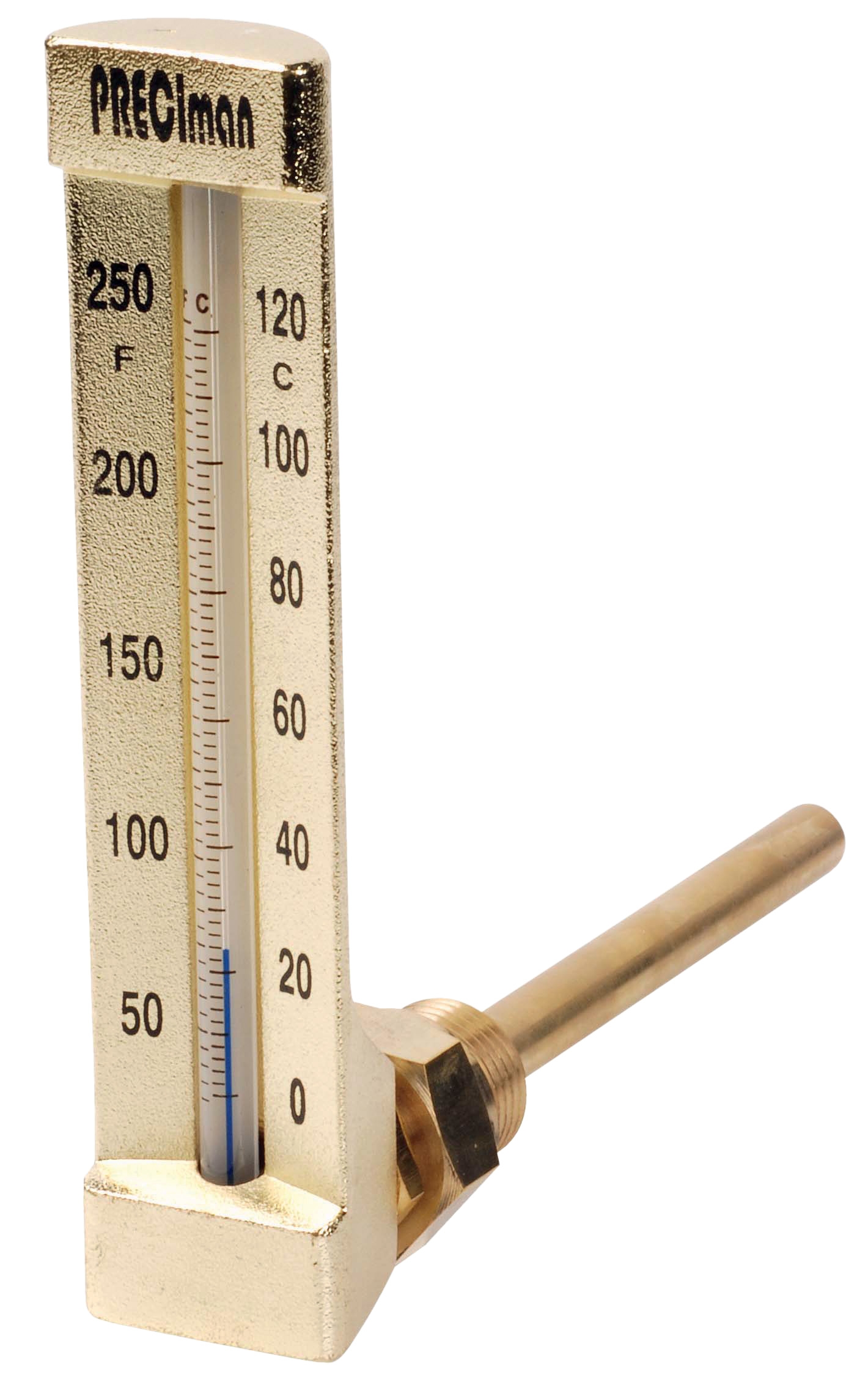
- Verify the selected thermometer matches the application temperature range
- The CBM Green vertical thermometer D80 -30/+50°C L 10cm with thermowell serves applications requiring broader range visibility
- The CBM Industrial thermometer 0/+50°C immersion 63 right angle height 150 suits standard heating system applications
- Select thermometers with 20-30% of their range above and below expected operating temperatures for best accuracy
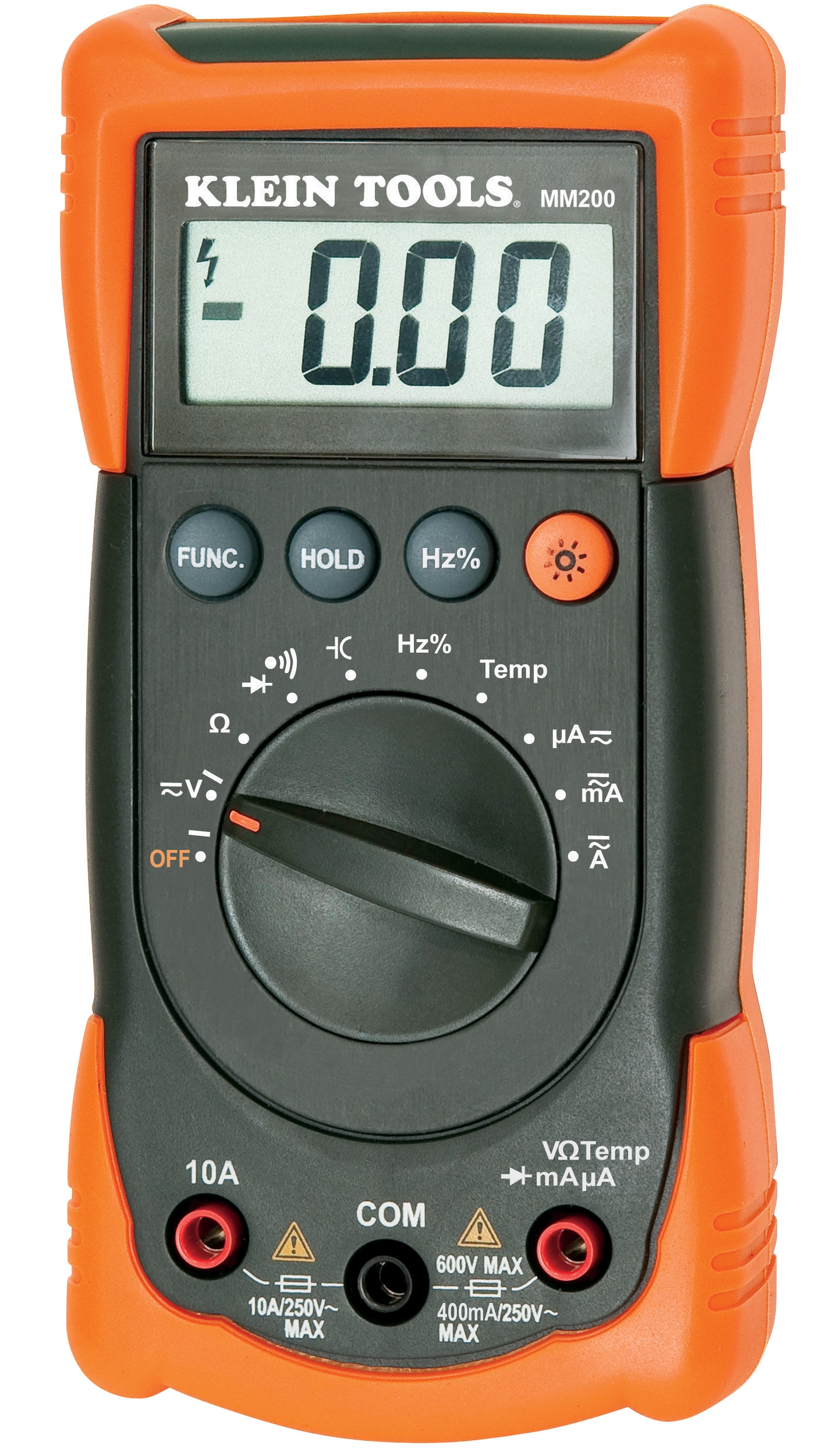
Section 2: Electrical Measurement Instrument Troubleshooting
Electrical Measurement Failures in Industrial Context
Electrical measurement failures often cascade into system shutdowns because operators cannot verify voltage, current, or continuity status. The most common failures include battery depletion, input overload damage, and software calibration corruption.
Automatic multimeters like the CBM Automatic multimeter MM420 streamline measurements by automatically selecting ranges and functions, but this automation can mask underlying issues that manual multimeters would reveal immediately.
Electrical Measurement Troubleshooting Procedure
Step 1: Battery and Power Status Verification
- Check battery indicator on the multimeter display
- If indicator shows low battery, replace batteries immediately (do not assume meter remains accurate on low power)
- Verify correct battery type and polarity
- Clean battery contacts with dry cotton swab to ensure proper connection
- Test multimeter on known voltage source (wall outlet or equipment data plate reference) after battery replacement
- Identify the last measurement that was taken
- Review the measurement range that was selected
- Confirm the actual voltage or current at that location didn't exceed the selected range by more than 10%
- If overvoltage or overcurrent was applied, the input circuit may have activated protective fuses
- Test continuity mode to verify internal fuse integrity
- Consult the multimeter manual for fuse replacement procedures (some fuses require technician-level access)
- Perform measurements on known reference sources across three voltage ranges (low: 0-10V, medium: 10-100V, high: 100-1000V)
- Auto-range instruments should display readings within ±0.5% of reference values
- If readings drift by >1%, the auto-range algorithm may have calibration drift
- Manual range selection on suspected measurements can help isolate whether the failure is in auto-range logic or the measurement circuits themselves
- Inspect probe tips for oxidation, pitting, or corrosion (green or white deposits indicate oxidation)
- Gently rub probe tips on cotton fabric to remove light oxidation
- For heavy oxidation, use fine sandpaper (1000+ grit) in one direction only
- Test probes for continuity with multimeter in continuity mode (should show <1Ω resistance)
- Replace probes if they show cracked insulation or bent tips
- Disconnect the multimeter from all circuits
- Test continuity between probe tips (should show open circuit with no connection)
- Measure multimeter's own resistance across all input terminals (should show >10MΩ in DC voltage mode)
- If measurements are abnormal, the input circuits may have sustained damage requiring factory repair
Section 3: Expansion Tank Monitoring and Inflation System Issues
Expansion Tank Failure Impacts and Detection
Expansion tank systems maintain proper pressure in closed-loop heating and cooling systems. When inflation systems fail, pressures drift, causing cavitation, premature pump wear, and potential system rupture. The CBM Expansion tank inflator battery 2000 mAH provides portable diagnostics for these critical systems.
Expansion tank failures originate from three sources: incorrect initial pressurization, air leakage causing pressure loss, and diaphragm rupture creating internal contamination.
Expansion Tank System Troubleshooting Procedure
Step 1: System Pressure Baseline Documentation
- Record current pressure reading from the system gauge
- Document ambient temperature (pressure changes approximately 0.3 PSI per degree Celsius)
- Note the system's design operating pressure from documentation or equipment nameplate
- Typical heating systems operate 30-40 PSI; cooling systems 20-30 PSI; steam systems 15-100+ PSI depending on application
- If available, review pressure logs from the past 30 days
- Stable systems maintain pressure within ±2 PSI across daily temperature cycles
- Gradual pressure loss (1-2 PSI per week) indicates small air leakage from connections or valve stems
- Rapid pressure loss (>5 PSI per week) suggests major leakage or diaphragm rupture
- Erratic pressure swings indicate trapped air in distribution piping
- Close isolation valves on both sides of the expansion tank (typically a ball valve above and inline isolation valve below)
- Measure pressure in tank using specialized pressure gauge or diagnostic inflator
- Tank pressure should be 0.5-1.0 PSI below minimum system operating pressure
- If tank pressure equals system pressure, the internal diaphragm may have ruptured
- If tank pressure is extremely low (<2 PSI on a 30 PSI system), air has leaked from the tank air valve
- Locate the small air valve on the tank (resembles a tire valve)
- Using the CBM Expansion tank inflator battery 2000 mAH, press the nozzle against the valve for 3-5 seconds
- If air hisses out, the tank has excess air (system was over-pressurized during initial fill)
- If no air escapes but pressure increases, the valve seal is intact but tank was under-pressurized
- If air continuously leaks around the valve stem, the valve requires replacement
- Close all isolation valves on the expansion tank
- Drain system to bring pressure to approximately 10 PSI (or minimum stated pressure)
- Use the diagnostic inflator to pressurize tank air side to design pressure (typically 0.7× minimum system pressure)
- Slowly reopen isolation valves and monitor pressure gauge during initial pressure increase
- Pressure should stabilize within 5 minutes and remain steady for 24 hours
- If pressure continues drifting, investigate connection leaks using soapy water on all fittings
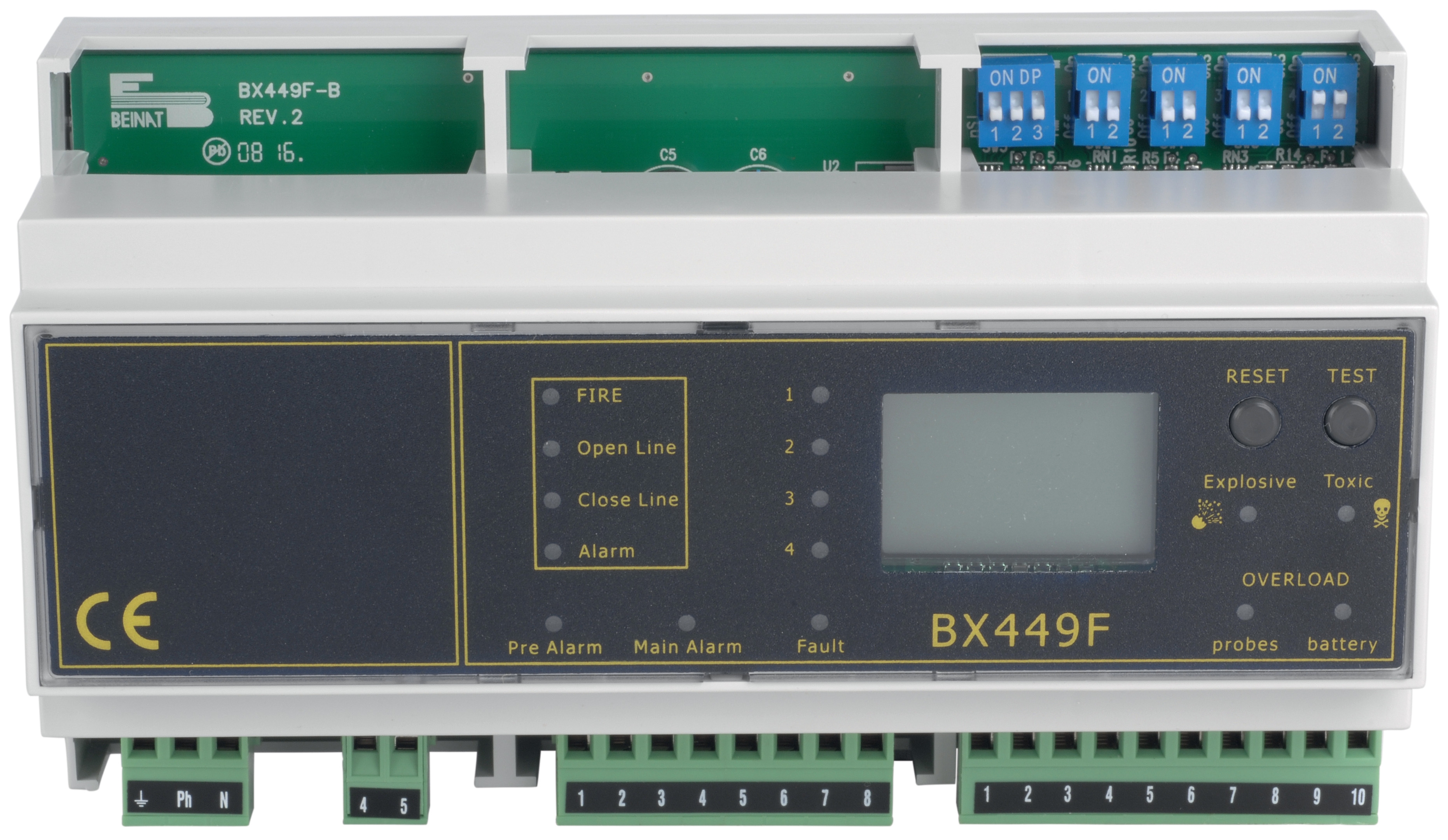
Section 4: Integrated Measurement System Troubleshooting and Cross-System Diagnostics
Why Multi-System Failures Occur
Industrial facilities typically integrate multiple measurement systems: temperature sensors feeding into control systems, pressure transmitters connected to safety interlocks, and electrical measurements monitoring equipment health. When one system fails, cascading effects often corrupt data from connected systems, making root cause diagnosis extremely difficult.
Integrated System Troubleshooting Procedure
Step 1: Establish Measurement System Hierarchy
- Create a diagram showing which measurement devices feed into which control or monitoring systems
- Identify the "primary" measurement (the one that controls the process) and "secondary" measurements (those that only monitor)
- Primary measurement failures typically trigger system shutdowns; secondary failures only affect visibility
- Prioritize troubleshooting primary measurements first
- Disconnect each measurement sensor from its control input (if safely possible during scheduled maintenance)
- Perform standalone measurements using reference instruments or direct observation
- A thermometer reading 50°C should confirm actual process temperature is approximately 50°C
- An electrical measurement showing 240V should correlate with equipment operating normally
- If the standalone measurement disagrees with the system reading, the problem lies in the measurement device or signal wiring
- For analog 4-20mA signals: Measure voltage drop across the signal wiring (should be <1V for distances <1000m)
- Check for damaged insulation on signal cables (should show >100MΩ resistance to ground)
- Verify signal connections are not shared with power wiring (separation >5cm minimum)
- Test continuity of shielding wires if cables are shielded (should show <1Ω resistance through the shield)
- Document current readings from all measurement points during stable operating conditions
- Create a reference table showing expected readings at 25%, 50%, and 75% of normal operating load
- Compare current measurements to this baseline at each operating point
- Significant deviations (>5% on any measurement) indicate calibration drift in one or more sensors
- Schedule calibration for drifted sensors before they cause control system instability
- Thermometer calibration: Annual verification against reference standards, cleaning every 6 months
- Electrical multimeter: Battery replacement semi-annually, probe inspection monthly
- Expansion tank systems: Pressure verification monthly, air valve inspection annually
- System documentation: Update measurement device inventory, calibration history, and replacement dates quarterly
Conclusion: Building Measurement System Reliability
Measurement and Detection system failures need not cause extended downtime when maintenance teams implement systematic troubleshooting procedures. The key is understanding that most failures arise not from equipment defects, but from installation inadequacies, environmental contamination, or calibration drift—all conditions that maintenance teams can identify and correct without replacing functional equipment.
3G Electric's 35+ years of experience distributing industrial measurement equipment has demonstrated that facilities implementing quarterly measurement system audits reduce unplanned downtime by 60% and avoid unnecessary replacement costs. By documenting baseline readings, monitoring trends, and performing the verification procedures outlined in this guide, your maintenance team transforms measurement systems from sources of uncertainty into reliable data sources that drive confident operational decisions.
The investment in systematic measurement troubleshooting pays dividends through improved equipment reliability, reduced energy consumption from optimized system operation, and most importantly, enhanced safety through accurate detection of hazardous conditions.