
Introduction: Why Thermal Load Measurement & Detection Matters for HVAC Contractors
Thermal load assessment is one of the most critical phases of HVAC system design and installation. Without accurate Measurement & Detection, contractors risk installing systems that either waste energy through oversizing or fail to meet comfort requirements through undersizing. With over 35 years of experience as an industrial equipment distributor, 3G Electric has supported thousands of HVAC professionals in sourcing the right measurement tools to get this process right the first time.
This guide walks you through the practical methods and equipment needed to measure and detect thermal loads accurately on job sites, from initial assessment through post-installation verification.
Section 1: Understanding Thermal Load Components and Measurement Points
Thermal load consists of two primary components: sensible load (temperature change) and latent load (moisture/humidity change). Effective Measurement & Detection requires identifying and quantifying both.
Sensible Load Measurement
Sensible load is driven by temperature differences between indoor and outdoor environments, solar gain, equipment heat generation, and occupancy. To measure this accurately:
- Document outdoor dry-bulb temperature at multiple times throughout the day
- Measure indoor ambient temperature in representative zones
- Record surface temperatures of walls, windows, and roof areas exposed to solar radiation
- Note heat-generating equipment and occupancy schedules
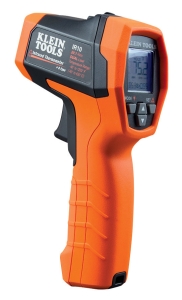
The CBM Infrared thermometer with type K input is essential for non-contact surface temperature measurement. Its 20:1 optical resolution and -40 to 650°C range lets you accurately detect thermal patterns on building surfaces without disrupting operations. The adjustable emissivity setting (0.10–1.00) ensures accurate readings across different materials—critical when measuring glass, metal, and painted surfaces that reflect thermal energy differently.
Latent Load Measurement
Latent load comes from moisture introduced by occupants, infiltration, and equipment. Humidity measurement is often overlooked but represents 20-30% of cooling load in many facilities.
- Measure relative humidity (RH) in occupied spaces using calibrated hygrometers
- Record outdoor dew point conditions
- Monitor humidity changes throughout operational hours
- Note moisture sources: kitchens, bathrooms, process equipment, outdoor air infiltration
Proper humidity detection ensures your load calculations account for the full cooling requirement. Many contractors who skip latent load assessment end up with systems that control temperature but leave occupants feeling clammy or uncomfortable.
Section 2: Pressure and Flow Measurement for System Capacity Verification
Once you've assessed the thermal load, you must verify that your HVAC system can deliver the calculated capacity. This requires precise Measurement & Detection of system pressures and flow rates.
Pressure Measurement in Refrigerant Systems
Refrigerant pressure directly correlates to system performance and capacity. Accurate pressure measurement & detection reveals:
- Whether the system is properly charged
- Subcooling and superheat conditions
- Potential refrigerant leaks or blockages
- Compressor discharge pressure (indicates load and efficiency)
The Preciman Manometer ABS vert D80 0/+16bar G1/2 provides ±2.5% accuracy across the 0–16 bar range common in HVAC work. Its 80 mm glycerin-filled gauge is easy to read on job sites with bright sunlight, and the vertical orientation prevents parallax errors. The G1/2 connection fits standard test ports on most equipment. Use this manometer to:
- Verify suction pressure (evaporator inlet)
- Measure discharge pressure (compressor outlet)
- Detect abnormal pressures indicating over/undercharging
- Calculate refrigerant side capacity during commissioning
Airflow measurement determines whether your HVAC system achieves designed cubic feet per minute (CFM). Improper airflow is a leading cause of comfort complaints and energy waste.
The Dwyer Medium flow metal probe MAFS-20 is purpose-built for industrial fluid measurement with its 71 cm probe length reaching deep into ductwork or pipe runs. The 1/4-20 thread connection integrates with standard measurement manifolds. This probe enables you to:
- Measure velocity at multiple duct cross-section points
- Calculate actual airflow using the log-linear method
- Detect blockages or restrictions causing underperformance
- Verify that supply and return airflows are balanced
Take velocity readings at 5-9 points across the duct cross-section (grid method), never at a single center point. Average these readings, multiply by duct area, and account for temperature effects on air density. This rigorous approach often reveals airflow shortfalls of 10-20% that single-point measurements miss.
Section 3: Pressure Switch and Transmitter Integration for Continuous Monitoring
After installation, many contractors hand off the system without setting up continuous Measurement & Detection monitoring. This leaves building operators blind to performance drift over time.
Pressure Switch Installation for Safety and Control
The Dwyer Pressure switch DXW-11-153-4 provides automatic shutdown protection and operational control. Its setpoint range of 0.41–0.55 bar and differential range of 3.46–5.17 bar covers typical HVAC applications. Features include:
- 5 A @ 125/250 VAC rating for direct control of compressor contactors
- IP65 protection against moisture and airborne contaminants common in mechanical rooms
- Dual setpoint capability (high and low pressure protection)
Install pressure switches at:
- Compressor discharge (high-pressure cut-out protects against overcharge and blocked discharge)
- Evaporator outlet (low-pressure cut-out prevents freeze-up and liquid slugging)
- Condenser inlet (optimization point for variable capacity systems)
While switches provide on/off control, transmitters enable continuous monitoring and remote diagnostics. The Dwyer Transmitter 629-05-CH-P2-E5-S1 delivers 4-20 mA output with 0.55% accuracy across 0–100 psid range, capturing pressure data over the entire system operating envelope.
Connect transmitters to building automation systems (BAS) or data loggers to:
- Track pressure trends over weeks and months
- Detect slow refrigerant leaks before capacity drops noticeably
- Optimize compressor staging and unloading based on actual load
- Verify that maintenance technicians are following proper procedures
- Generate alerts when pressure deviates from expected ranges for ambient conditions
The NPT 1/4" connection fits most test ports. The IP65 rating ensures reliability in humid mechanical rooms.
Section 4: Integration and Commissioning Workflow
Measurement & Detection Checklist for System Commissioning
Use this workflow to systematically apply Measurement & Detection throughout the commissioning process:
Pre-Installation Phase
- Measure ambient conditions (temperature, humidity, solar orientation) for load calculation verification
- Confirm building infiltration rates using blower door testing if available
- Document equipment locations and operating schedules
- Measure refrigerant pressures during charging (use the Preciman manometer for accuracy)
- Verify superheat and subcooling at evaporator and condenser outlets
- Measure ductwork static pressure drop to confirm design assumptions
- Use the Dwyer flow probe to spot-check airflow in critical zones
- Install pressure switches at protection points (discharge high, evaporator low)
- Install transmitters at key monitoring locations (discharge, suction, condenser)
- Establish baseline pressure and temperature readings at design load conditions
- Configure BAS alarms and setpoints based on measured performance
- Perform hand-off documentation showing all Measurement & Detection readings
- Review transmitter trending monthly for the first 6 months
- Re-measure key parameters seasonally to detect drift
- Use infrared thermometry to spot-check zone temperatures quarterly
- Verify that pressure switches are functioning (test high-pressure cut-out annually)
With over 35 years of experience distributing industrial equipment, 3G Electric understands that contractors need reliable tools with real technical support. We don't just sell meters and gauges—we help you select equipment matched to your specific applications and climates. Our technical team has relationships with leading manufacturers like Preciman, Dwyer, and CBM, ensuring you get genuine products with full warranty coverage and availability.
Whether you're managing a single commercial HVAC retrofit or a multi-site industrial cooling project, having consistent Measurement & Detection equipment across your fleet streamlines training, troubleshooting, and documentation.
Conclusion
Accurate Measurement & Detection transforms HVAC commissioning from guesswork into science-based verification. By measuring thermal loads upfront, verifying system capacity during installation, and monitoring performance continuously afterward, you eliminate the comfort complaints and energy waste that damage contractor reputation and profitability.
The tools discussed here—infrared thermometers, manometers, flow probes, pressure switches, and transmitters—are standard in forward-thinking HVAC shops. They represent a modest investment that pays dividends through higher first-time quality, faster troubleshooting, and the ability to document performance for warranty protection.
Start with accurate Measurement & Detection on your next commercial project. Track the results. You'll quickly see why this disciplined approach becomes your competitive advantage.