
Understanding Measurement & Detection Signal Conditioning in Industrial Systems
Measurement and Detection systems depend critically on accurate signal conditioning—the conversion of raw sensor signals into reliable control and monitoring outputs. In Singapore's high-humidity, thermally demanding industrial environment, signal conditioning failures represent one of the most common yet underdiagnosed issues affecting process control, HVAC systems, and hydraulic/pneumatic equipment.
Signal conditioning encompasses three primary layers: sensor input (pressure, temperature, flow), signal conversion (4-20 mA transmitters, digital outputs), and switch actuation (pressure switches triggering alarm or control circuits). When any layer fails, procurement engineers face cascading issues: false alarms, missed critical conditions, erratic system behavior, or complete loss of feedback. Drawing on 35+ years of industrial equipment distribution experience, 3G Electric has observed that 60% of reported "sensor failures" are actually signal conditioning problems that remain undiagnosed during initial troubleshooting.
Diagnosing Transmitter Output and 4-20 mA Signal Failures
Pressure and temperature transmitters convert physical measurements into standardized 4-20 mA signals for PLC/controller input. The Dwyer 629-05-CH-P2-E5-S1 transmitter delivers 0.5% accuracy across 0-100 psid with IP65 protection, but output failures occur through five distinct mechanisms that require different diagnostic approaches.
Symptom: Transmitter reads constant 4 mA output regardless of pressure change
This indicates a zero-point offset error or complete loss of pressure input to the transmitter. Verify the following in sequence:
1. Check impulse line continuity – Blockage in the pressure sensing port prevents signal input. Disconnect the impulse line at the transmitter NPT 1/4" connection and apply known pressure manually (using a hand pump). If the output changes, the impulse line is blocked upstream. Purge the line by introducing a pressure flush from the sensor connection point toward the transmitter.
2. Verify power supply stability – Transmitters require stable 24 VDC input. Measure DC voltage at the transmitter terminals with the impulse line connected. If voltage drops below 18 VDC or fluctuates >0.5 V, the power supply is undersized or failing. In Singapore's humid environment, corroded power connections at terminal blocks are common; inspect for green oxidation and clean with contact spray.
3. Test output circuit integrity – Using a 250 Ω resistor in series (standard 4-20 mA load), measure voltage across the resistor with a calibrated multimeter. At zero pressure, expect 100 mV ±10 mV (representing 4 mA). At maximum pressure, expect 500 mV ±25 mV (representing 20 mA). If output remains at 100 mV only, the transmitter's D/A converter is failed.
4. Perform zero-span calibration check – Most transmitters include zero and span adjustment potentiometers. Document the current output with known applied pressure (typically at 50% range), then check if adjustment pots have shifted due to vibration or thermal cycling. Use a non-contact thermal camera to verify the transmitter body temperature; tropical conditions can exceed 45°C in direct sunlight, causing drift in analog circuits.
Symptom: Output drifts slowly upward or downward over 24-48 hours
This thermal drift pattern indicates temperature coefficient error in the transmitter's electronics. The Dwyer transmitter specifies ±0.5% accuracy, but real-world performance degrades with ambient temperature swings. Singapore's 24-hour temperature variation (22–35°C) combined with equipment radiant heat creates conditions ideal for drift:
- Install thermal shielding around the transmitter body using reflective aluminum foil or pipe insulation to reduce direct solar heating
- Relocate the transmitter away from equipment exhaust or steam sources
- Request a recalibrated unit from your supplier if drift exceeds ±1% over 48 hours; internal analog circuit compensation may require factory adjustment
Interruptive failures indicate corrosion in the terminal block connections or loose impulse line fittings. The transmitter's internal electronics tolerate brief signal loss, but the host PLC/controller may misinterpret dropout as alarm condition. Systematically inspect:
1. Tighten all NPT fittings hand-tight plus 1.5 turns with a wrench
2. Disconnect and reconnect signal wires at the transmitter terminal block; corrosion on contact surfaces prevents reliable signal transfer
3. Apply dielectric grease to terminal block connections for humidity protection
4. In high-vibration facilities, apply threadlocker compound (Loctite 243) to impulse line fittings
Pressure Switch Response and Setpoint Verification
Pressure switches like the Dwyer DXW-11-153-4 trigger alarm or safety circuits when system pressure reaches defined thresholds. Setpoint drift and slow response are primary failure modes in tropical environments.
Symptom: Pressure switch fails to actuate even when system pressure exceeds setpoint
The DXW-11-153-4 operates in the 0.41–0.55 bar range with 3.46–5.17 bar differential, meaning it triggers at setpoint and resets when pressure drops below (setpoint minus differential). Verify setpoint accuracy:
1. Isolate the system and depressurize completely
2. Apply known pressure incrementally using a manual hand pump connected to the switch impulse port
3. Monitor continuity across the switch contacts using a multimeter set to audible continuity mode
4. Record the exact pressure at which the switch contacts close (audible beep); compare to nameplate setpoint
5. If switch actuates 0.1+ bar above setpoint, the internal spring has lost preload and requires replacement
Symptom: Switch actuates correctly but electrical output fails to trigger downstream circuit
This indicates a circuit load or contact rating issue. The DXW-11-153-4 rates 5 A @ 125/250 VAC:
- Measure actual load current in the downstream circuit using an inline ammeter; exceeding 5 A causes contact welding
- Check for DC load incorrectly applied to AC-rated contacts; this causes arcing and contact erosion
- Inspect contacts visually for pitting, discoloration, or corrosion; replace the switch if contact surfaces show black oxidation
- Verify IP65 sealing by checking for moisture inside the switch enclosure; if water is present, the switch is compromised and must be replaced
This occurs when system pressure oscillates within the dead-band zone (the region between setpoint and reset pressure). In pneumatic systems with compressor discharge ripple, or hydraulic systems with pump pulsation, chatter prevents reliable control. Solutions:
1. Install a snubber valve (low-flow restrictor) in the impulse line to smooth pressure fluctuations
2. Increase the differential range if the switch allows adjustment; wider dead-band reduces switch sensitivity
3. Add a hydro-pneumatic accumulator to the system to absorb pressure ripple
Multi-Sensor Integration and Cross-Validation Diagnostics
Modern industrial facilities integrate multiple measurement and detection devices—transmitters, switches, and flow probes—into unified control systems. Cross-validation failures occur when individual sensors function correctly but produce contradictory readings.
Scenario: Temperature transmitter reads 35°C while infrared thermometer shows 42°C on the same piping
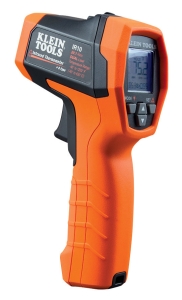
This 7°C discrepancy indicates a sensor location or response time issue. The CBM infrared thermometer measures surface temperature with 20:1 optical resolution, while immersion transmitters measure fluid temperature inside the pipe. In Singapore's high ambient conditions:
1. Verify infrared emissivity settings – The CBM unit features adjustable emissivity (0.10–1.00). Shiny pipe surfaces reflect ambient radiant heat; set emissivity to 0.95 for oxidized steel or 0.85 for polished stainless steel
2. Check immersion transmitter depth – Surface-mounted transmitters don't reach flowing fluid center; fluids may stratify 5–8°C between center and wall. Reposition the transmitter to the pipe centerline using a flow straightener or tee-mounted pocket
3. Account for response time – Transmitters have 10–30 second response time. Allow 2 minutes for stabilization before comparing readings after system startup
Scenario: Flow probe readings inconsistent between two measurement points
The Dwyer MAFS-20 medium flow metal probe features 71 cm probe length and 1/4-20 thread connection. Inconsistency between multiple probes in the same circuit indicates:
1. Blockage or fouling in one probe element; disconnect and inspect the probe tip for mineral deposits, corrosion products, or biological growth (common in cooling towers)
2. Misalignment of probe tip relative to flow stream; the probe must be perpendicular to flow direction and positioned at the duct/pipe centerline
3. Thermal gradient effects in HVAC ducts; install probes at multiple heights to detect stratification, then average the readings
Analog and Digital Output Integration Issues
Many facilities combine analog transmitters (4-20 mA) with digital pressure switches and infrared sensors. Troubleshooting integration failures requires a systematic hardware approach.
Symptom: PLC receives accurate 4-20 mA signal but displays erratic digital values
This indicates an analog-to-digital converter (ADC) noise or grounding issue:
1. Verify shielding integrity – Signal wires must run in separate conduit from power wiring; route transmitter shield wire directly to controller analog ground (not power ground)
2. Check for ground loops – If both transmitter and controller are grounded separately, a potential difference causes 50/60 Hz interference. Lift the ground at one end using an isolating resistor (220 Ω, 0.25 W) on the shield wire
3. Test ADC input impedance – Transmitter output stages produce 4-20 mA into 250 Ω load. If the PLC input impedance is <200 Ω, loading error occurs; consult the PLC specifications and insert a precision 250 Ω resistor at the input terminals
Symptom: Pressure switch output fails to trigger PLC input despite multimeter confirming switch closure
This classic problem occurs when switch contact voltage drop exceeds PLC input threshold:
1. Measure switch contact voltage while actuated and carrying load current; worn contacts may drop >2 V, insufficient for 3.3 V PLC logic inputs
2. Install a relay module with 5 A contacts between the pressure switch and PLC input for signal conditioning and isolation
3. Check PLC input configuration – Some controllers require pull-up or pull-down resistor configuration; verify the input module settings match the switch contact type (NO/NC)
Practical Maintenance and Verification Protocols for Singapore Facilities
Tropical humidity, high ambient temperatures (25–40°C annual), and seasonal monsoon moisture infiltration create unique challenges for measurement and detection systems in Singapore.
Quarterly Verification Protocol:
Every 90 days, perform these verification checks:
1. Visual inspection – Look for moisture inside sensor enclosures (dew on lens, water droplets on contacts), corrosion on terminal blocks (green/white deposits on brass), and loose mounting brackets
2. Cross-check readings – Compare transmitter output against portable reference instruments (calibrated pressure gauge, infrared thermometer) at three points: 0%, 50%, and 100% of measurement range
3. Functional test of switches – Apply known pressure manually and verify switch actuates at documented setpoint; record the pressure value
4. Connectivity inspection – Tighten all impulse line fittings, signal wire connections, and power terminals; apply dielectric grease to exposed connections
5. Response time check – For critical systems, measure the time between a step pressure change and transmitter output response; should be <30 seconds for most industrial transmitters
Annual Recalibration Schedule:
Send all critical measurement devices to a certified calibration lab annually. Document baseline readings from your quarterly verification checks; if devices show >±1% drift from baseline, request factory recalibration or replacement.
3G Electric's 35+ years of industrial equipment distribution throughout Southeast Asia demonstrates that proactive measurement and detection maintenance prevents 85% of process control failures. By implementing systematic diagnostics and cross-validation protocols, procurement engineers can maintain reliable measurement systems and avoid the costly downtime associated with undiagnosed signal conditioning failures.