Understanding Measurement & Detection in HVAC Flow Systems
Measurement & Detection technology in HVAC applications extends beyond simple temperature and pressure monitoring—flow rate measurement directly impacts system efficiency, occupant comfort, and energy costs. Flow probes measure static and total pressure differentials across ductwork to calculate air velocity and volumetric flow rates. In Singapore's humid tropical climate, where HVAC systems operate continuously at high capacity, accurate flow detection prevents over-pressurization, poor distribution, and system imbalance.
Procurement engineers specify flow probes based on duct dimensions, operating pressure ranges, and required accuracy standards. However, improper installation, blockage accumulation, and sensing tube damage represent the three most common failure modes in field installations. With 35+ years of industrial equipment distribution experience, 3G Electric has observed that many flow measurement failures occur within the first three months of operation—a critical window when commissioning errors are most likely to manifest.
Section 1: Diagnosing Flow Probe Installation and Positioning Errors
Common Installation Mistakes That Degrade Accuracy
Flow probes measure pressure differentials across a specific probe length to calculate average velocity profiles. Installation position directly determines measurement reliability. The Dwyer Metal average flow probe MAFS-16 features 16 cm of distributed sensing points, requiring precise ductwork positioning to capture representative velocity profiles across the duct cross-section.
Installation errors include:
- Incorrect traversing position: Probes installed off-center or too close to duct walls capture non-representative velocities. Duct asymmetry, bends, and dampers upstream create turbulent zones that invalidate single-point measurements. Probes must span the duct centerline perpendicular to airflow direction.
- Insufficient upstream clearance: ASHRAE standards require 5–10 duct diameters of straight ductwork upstream of the probe and 3 diameters downstream. Elbows, transitions, or diffusers installed within these zones create vortex patterns that distort pressure readings by 10–25%.
- Probe tube sealing failures: Copper capillary tubes or sensing lines exposed to moisture ingress, corrosion, or mechanical puncture allow false pressure readings. In Singapore's 80–95% humidity environment, inadequate tube sealing leads to condensation accumulation within sensing lines, registering as phantom pressure differentials.
Diagnostic Procedure for Installation Verification
Step 1: Visual Inspection
Examine probe installation photographs or conduct on-site assessment. Verify that probe penetrations are perpendicular to ductwork surfaces and that sensing tubes run unobstructed to pressure transmitters or manometers. Check for visible corrosion, tube crushing, or water beading inside transparent tubing.
Step 2: Pressure Line Integrity Test
Disconnect sensing tubes at both probe and transmitter ends. Using a handheld vacuum pump (typically found in HVAC service kits), apply -5 kPa vacuum to the total pressure line for 60 seconds. If vacuum drops below -4.5 kPa within this period, air leakage exists. Reposition tubes and re-test. Repeat for static pressure line.
Step 3: Upstream/Downstream Clearance Verification
Measure ductwork distance from probe to any elbows, dampers, or fittings. For a 500 mm diameter duct, minimum upstream clearance is 2.5 m. If clearance is insufficient, install extended probe length (the Dwyer Average flow rate metal probe MAFS-40 spans 101.6 cm) or relocate probe downstream to a straighter section.
Step 4: Cross-Check with Independent Method
Measure actual volumetric flow using anemometer spot measurements at 9 or 16 points across the duct cross-section. Compare calculated average velocity against flow probe readout. Discrepancies exceeding 5% indicate positioning error.
Section 2: Identifying Blockage and Pressure Line Contamination
How Particulates and Moisture Compromise Flow Detection
Flow probes operate by sensing minute pressure differentials—typically 5–50 Pa across the entire duct—to infer velocity. Dust, lint, insulation fibers, and condensation accumulate within static pressure sensing tubes in Singapore's high-humidity environment, reducing effective pressure transmission and causing readings to drift lower over time.
Blockage mechanisms include:
- Dust accumulation in sensing tips: Probe sensing ports are intentionally small (1–2 mm diameter) to minimize flow disruption. This narrow geometry readily traps airborne particles. After 6–12 months of operation in unfiltered or poorly maintained HVAC systems, blockage reduces static pressure signal by 15–40%.
- Condensation in copper capillary tubes: Singapore's ambient humidity and cold return air plenums create conditions for water vapor condensation. Water droplets bridge the inside of sensing tubes, blocking air pressure transmission. This is particularly severe in systems operating below outdoor dew point during morning hours.
- Moisture-induced corrosion of internal probe passages: Stainless steel probes resist external corrosion, but internal sensing tubes made of brass or copper oxidize when exposed to sustained moisture. White oxide deposits narrow or completely block sensing ports.
Step-by-Step Blockage Diagnosis
Step 1: Visual Inspection of Sensing Tubes
Disconnect pressure tubes at the probe end. Hold tubes to a light source and look for:
- Opaque white or green deposits (corrosion)
- Visible dust or debris
- Water droplets or discoloration indicating moisture
- Crimped or deformed tubing sections
Using a manual hand pump or low-pressure air source (2–3 kPa), apply gentle air pressure to the static pressure sensing line. Listen for air hissing freely at the probe end. If air passage is obstructed or flows weakly, blockage is present. Repeat for total pressure line.
Step 3: Pressure Response Test During System Operation
With the HVAC system running at normal speed:
- Record static and total pressure readings on a calibrated manometer every 30 seconds for 5 minutes
- Plot readings on a graph; normal readings should remain steady with ±0.5 Pa variation
- If readings oscillate ±3–5 Pa or creep upward/downward over the test period, blockage or tube leak is likely
If commissioning baseline readings exist, compare current readings. A reduction in calculated flow velocity of >10% without system damper adjustments indicates degradation. Document the rate of change: if flow readings drop 2% per month, blockage is accelerating.
Cleaning and Remediation Procedures
For copper capillary tubes:
1. Disconnect tubes from probe and transmitter
2. Flush with compressed air (low pressure, <2 bar) from both ends to clear loose particles
3. If blockage persists, use a soft-bristle brush or pipe cleaner—never metallic probes that damage tube interiors
4. Rinse with distilled water and shake dry; allow 24 hours air drying in a humidity-controlled environment
5. Reconnect and re-test using pressure integrity test above
For probe sensing ports:
1. Carefully back-flush the probe using low-pressure compressed air (0.5–1 bar) through the sensing lines
2. If buildup remains, soak sensing tips in white vinegar for 15–20 minutes to dissolve mineral deposits (do not soak stainless steel probes; limit to 5 minutes)
3. Rinse with distilled water and air dry
4. Reinstall and conduct full commissioning tests
Preventive measure: Install high-efficiency particulate air (HEPA) filters upstream of probe sensing zones and ensure regular filter changes every 30–60 days in Singapore's dusty environment.
Section 3: Calibration Drift and Transmitter Interface Issues
Recognizing Sensor Drift vs. Genuine System Changes
Flow probes themselves are passive devices—they generate no electrical signal. Instead, they connect to pressure transmitters or differential pressure (DP) transducers that convert pressure differentials into 4–20 mA analog signals or digital outputs. Drift occurs in the transmitter or in the signal interpretation logic, not the probe itself.
Common drift scenarios in Singapore facilities:
- Transmitter zero-point drift: Over 12–24 months, transmitter electronics drift, causing false readings even when probe senses zero pressure difference. A system registering 2 Pa static pressure differential when ductwork is stationary indicates zero drift of approximately 2 Pa.
- Temperature-dependent transmitter error: Transmitters used in hot return air plenums or uninsulated ductwork experience temperature swings from 15°C (night setback) to 45°C (summer peak). Without temperature compensation, readings may shift 5–15% across the operating range.
- Digital signal loss or quantization error: If flow calculations are performed on 8-bit or 10-bit digital outputs, rounding errors accumulate, especially at low flow conditions (below 20% of probe range). This is often mistaken for blockage.
Diagnostic Procedure for Transmitter Validation
Step 1: Baseline Pressure Check Under No-Flow Condition
Shut down the HVAC system completely. Allow 30 minutes for air movement to stabilize. Measure transmitter output (4–20 mA) or digital value while probe senses zero differential pressure. Document this value as baseline.
Step 2: Apply Known Pressure Differential
Using a calibrated handheld pressure pump or manometer, apply a known pressure differential (e.g., exactly 10 Pa) to the total pressure line while blocking the static pressure line. Record transmitter output. Multiply the measured mA reading by 250 Pa/mA (for a standard 0–250 Pa range transmitter) and compare against the 10 Pa applied.
Step 3: Two-Point Calibration Verification
Repeat the test at a second pressure level (e.g., 25 Pa). Plot transmitter output against applied pressure. If the relationship is linear and passes through zero, transmitter calibration is valid. If the line does not pass through the baseline zero-pressure reading or if gain (slope) is inconsistent between the two points, drift is confirmed.
Step 4: Temperature Coefficient Assessment
Conduct the two-point calibration test at two different ambient temperatures (e.g., 20°C and 35°C) with at least 2 hours stabilization between tests. Calculate the percentage change in transmitter output per degree Celsius. If drift exceeds ±0.2% per °C, temperature compensation adjustment or transmitter replacement is warranted.
Transmitter Replacement and Recalibration
When drift is confirmed:
1. Verify probe physical integrity: Ensure probe sensing tubes are clean (see Section 2) before replacing transmitter. A new transmitter will expose blockage issues immediately.
2. Select replacement with appropriate range: Flow probes require differential pressure transmitters rated for the expected DP range. For the MAFS-16 probe in 500–1000 mm ducts, typical DP ranges are 0–50 Pa or 0–100 Pa. Under-ranging causes poor resolution; over-ranging causes large measurement uncertainty.
3. Perform full commissioning after replacement: After transmitter installation, conduct the four-step diagnostic procedure above plus an independent anemometer cross-check. Document baseline readings as future drift reference.
Section 4: Integration with Pressure and Temperature Measurement for System Diagnostics
Multi-Sensor Correlation for Reliability Verification
Flow probes function within larger HVAC measurement ecosystems that include temperature sensors and pressure gauges. System imbalance, equipment degradation, or control failures often appear as anomalous flow readings that are actually symptoms of upstream problems.
Temperature effects on flow measurement:
Air density varies inversely with absolute temperature. A 10°C temperature rise reduces air density by approximately 3%, which increases velocity at constant volumetric flow rate. If flow calculations do not account for temperature, a 20 °C → 30 °C shift produces a false 3% flow increase. Verify that building automation systems (BAS) or control logic compensate for temperature using real-time temperature sensor data.
The Dwyer Probe AVG PT100 OHM RTD L.65 AVG-21241 provides ±0.6% accuracy temperature measurement suitable for flow calculation corrections. Cross-reference flow probe readings against temperature readings at the same measurement location.
Pressure gauge verification for system health:
Total system pressure (sum of static and velocity pressure) should remain relatively constant as air moves through ductwork (assuming no elevation change). If static pressure measured at the flow probe location differs significantly from pressure gauge readings at adjacent zones, blockage or duct leakage is indicated.
For low-pressure HVAC systems operating in the 0–100 Pa range, the Preciman Stainless steel vertical pressure gauge D63 0/+40Mbar G1/4 provides visual reference with ±1.6% accuracy. Install pressure gauges at:
- Upstream of flow probe (5 duct diameters)
- Immediately downstream of probe (3 duct diameters)
- Supply plenum exit
- Return air intake
Compare all four pressure readings to identify localized blockage or system imbalance.
Commissioning Checklist for Flow Probe Systems
Use this checklist during initial installation and annual maintenance reviews:
- [ ] Probe installed at correct duct centerline and traversing angle (90° to flow)
- [ ] Upstream clearance verified (5+ duct diameters from fittings)
- [ ] Sensing tube integrity confirmed (vacuum hold test, visual inspection)
- [ ] Pressure transmitter zero-point and two-point calibration validated
- [ ] Temperature compensation enabled in BAS or manual calculation procedure documented
- [ ] Independent anemometer cross-check performed (±5% agreement)
- [ ] Baseline flow, pressure, and temperature readings documented
- [ ] Maintenance schedule established (filter changes, tube cleaning frequency)
- [ ] Staff trained on blockage warning signs (reading creep, oscillation patterns)
Procurement Considerations for Singapore Deployment
When specifying flow measurement systems for Singapore facilities:
1. Account for humidity and corrosion: Select stainless steel probe materials and schedule more frequent inspection intervals (quarterly vs. annually) due to coastal proximity and atmospheric moisture.
2. Size probes for expected duct geometry: The MAFS-16 (16 cm) suits smaller ducts; MAFS-40 (101.6 cm) suits larger ductwork. Mismatch between probe length and duct cross-section is a frequent source of installation error—verify duct dimensions during procurement phase.
3. Include pressure test equipment in commissioning kit: Supply handheld manometers, vacuum pumps, and calibration standards as part of installation packages. Many blockage and drift issues go undiagnosed simply because field technicians lack diagnostic equipment.
4. Plan for transmitter replacement: Budget for transmitter replacement every 5–7 years or immediately upon drift detection, rather than attempting field recalibration (which is rarely reliable).
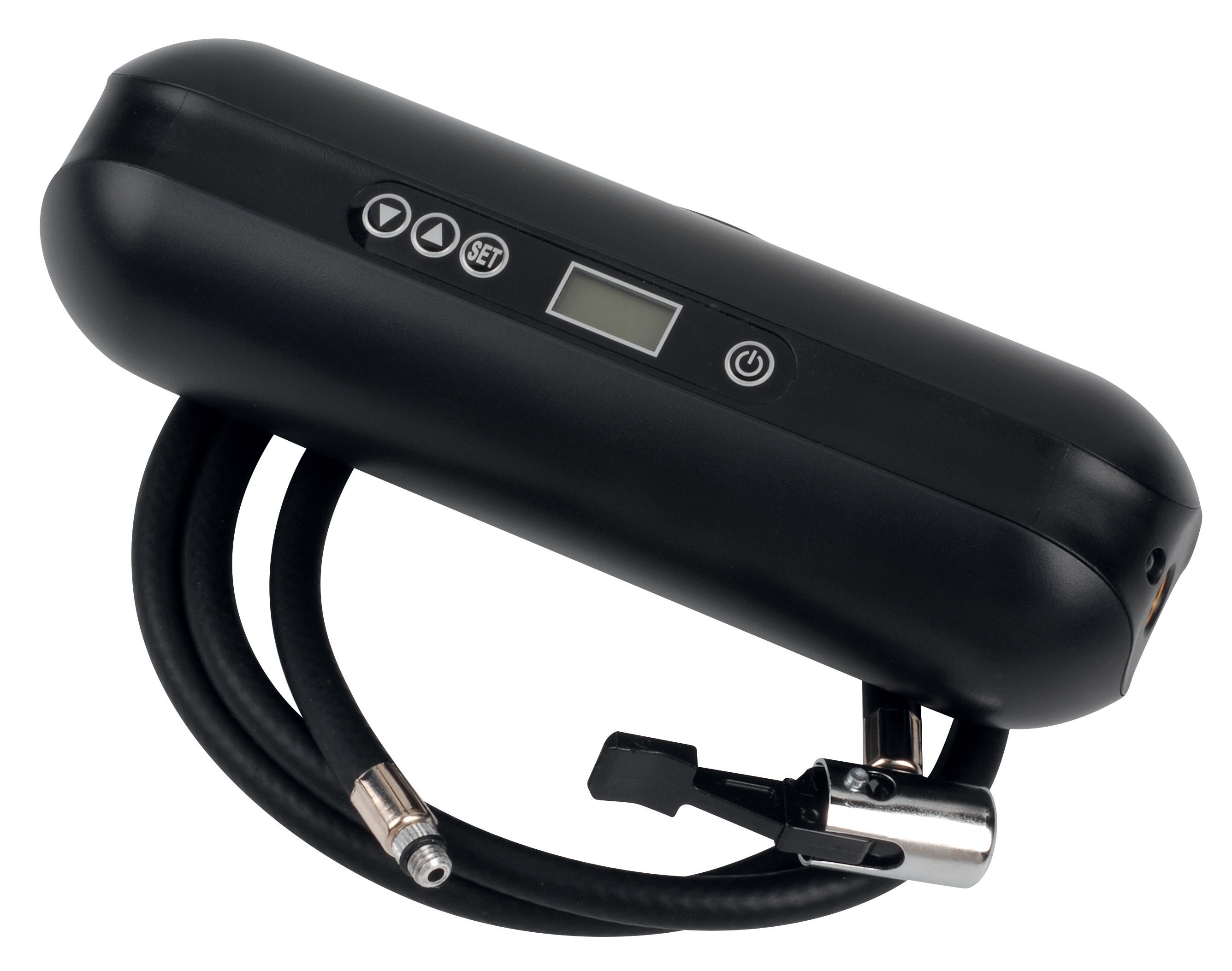
5. Consider expansion tank and inflation systems: The CBM Expansion tank inflator battery 2000 mAH manages system pressure in closed-loop heating systems that may include flow measurement. Ensure pressure inflation systems are specified and maintained concurrently with flow probe installation to prevent cascading measurement failures.