Understanding Component-Level Maintenance & Service Requirements
Maintenance & Service in industrial heating systems extends beyond routine cleaning—it demands a systematic approach to component inspection, performance diagnostics, and scheduled replacements that directly impact operational efficiency and safety. With over 35 years of global equipment distribution experience, 3G Electric has documented that approximately 60% of unexpected system failures stem from inadequate maintenance of secondary components rather than primary burner units.
The complexity of modern heating systems means maintenance teams must understand the interdependence of components across fuel delivery, combustion control, and safety systems. Each component operates within specific pressure ranges, temperature tolerances, and duty cycles. When one element degrades, downstream components experience accelerated wear. For example, a partially clogged nozzle increases back-pressure on the fuel supply, forcing the pump to work harder and reducing overall system efficiency while generating excessive heat in adjacent fuel lines.
Effective Maintenance & Service protocols require three critical competencies: baseline performance documentation, predictable failure pattern recognition, and rapid component isolation and replacement. Maintenance teams working with industrial burner systems must develop proficiency in reading pressure gauges, understanding combustion efficiency metrics, and interpreting diagnostic sensor data. This foundation enables teams to transition from reactive emergency repairs to proactive scheduled maintenance that reduces downtime and extends component lifecycles.
Nozzle Diagnostics and Replacement Protocols
High-pressure flat jet nozzles represent one of the most critical yet frequently overlooked maintenance points in burner systems. These components operate under extreme conditions—pressures often exceeding 250 bar with fuel spray patterns that must remain geometrically precise for efficient combustion. The CBM Flat jet nozzle HP 1/4"M BSPT index 25 angle 15° and CBM Flat jet nozzle HP 1/4"M BSPT index 055 angle 15° exemplify the precision engineering required, with carefully calibrated spray angles that determine flame shape and heat distribution patterns.
Diagnostic indicators that nozzle replacement is required include:
- Flame shape deterioration: Observable shift from uniform cone pattern to irregular or asymmetrical spray geometry
- Increased fuel consumption: Efficiency drops above 5% without corresponding load increases
- Elevated combustion temperatures: Localized heat zones indicating incomplete atomization
- Visible carbon deposits: Buildup around nozzle tip suggesting incomplete combustion and fuel starvation
- Pressure gauge fluctuations: Rapid oscillations indicating internal erosion or tip degradation
Replacement protocols demand precision and systematic documentation. Before removal, record baseline operating parameters: fuel pressure at the nozzle connection, combustion efficiency reading (CO₂ and O₂ levels), and flame observation notes including color and stability. This documentation establishes the before-condition for comparison with post-replacement performance verification.
Nozzle installation requires attention to thread engagement—the 1/4" BSPT male connection must achieve complete seal without over-torquing, which can damage precision-machined seating surfaces. Maintenance teams should use calibrated torque wrenches set to manufacturer specifications (typically 15-20 Nm for nozzle connections). Apply thread sealant only to the first two threads to prevent sealant migration into fuel passages. After installation, verify spray pattern during commissioning by observing the flame shape through the sight glass at idle and full-load conditions.
Nozzle index specifications (25 and 055 in our referenced products) determine spray angle and fuel delivery rate. Index 25 produces narrower, tighter spray patterns suitable for compact combustion chambers, while index 055 generates broader patterns for larger chambers. Substituting incorrect indices causes flame stability problems and poor combustion efficiency. Maintain a component matrix documenting which nozzle indices are matched to specific boiler models in your facility—this prevents installation errors during emergency replacements.
Fuel System Component Maintenance and Diagnostic Isolation
The fuel delivery system represents an interconnected network where each component influences downstream performance. Effective Maintenance & Service requires understanding how components interact and developing diagnostic protocols to isolate failing elements without replacing entire assemblies.
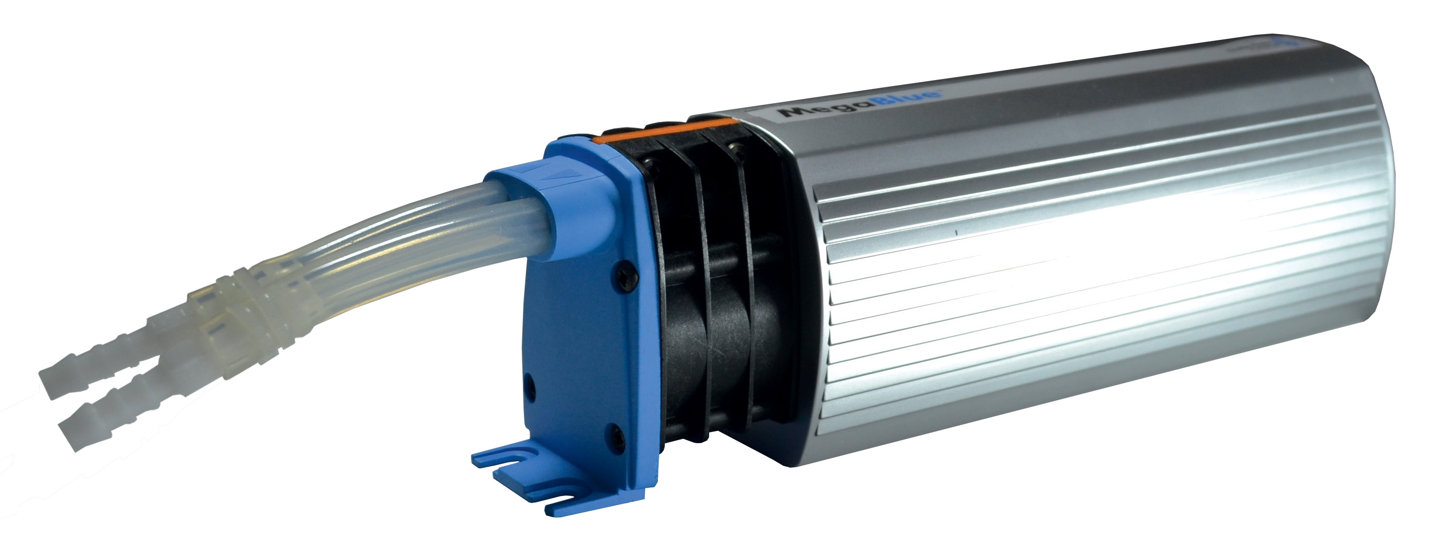
Expansion Tank Systems: The CBM Expansion tank inflator battery 2000 mAH addresses a frequently neglected maintenance requirement—maintaining correct expansion tank pre-charge pressure. Fuel systems include expansion tanks that accommodate volume changes from temperature fluctuations. These tanks require periodic pressure verification and inflation adjustment. Incorrect pre-charge pressure (either too low or excessive) causes erratic fuel pressure behavior that maintenance teams often misdiagnose as pump failure.
Diagnostic procedure: Isolate the expansion tank from the main fuel line using the service isolation valve. Connect a tire pressure gauge to the tank valve and record the reading. Compare against the system specifications, typically 1.5-2.0 bar for most burner systems. If pressure has dropped below specification, the tank bladder has likely degraded and requires replacement. If pressure is excessive (above 2.5 bar), manual deflation using the inflator battery restores system stability. Document all pressure adjustments in your maintenance log—pressure drift trends often indicate imminent tank failure warranting proactive replacement scheduling.
Reservoir Safety Systems: The CBM Megablue reservoir alarm + shut-off X87-813 provides dual protection—audible alarm notification of abnormal fuel levels and automatic fuel isolation to prevent overfilling or starvation conditions. Maintenance & Service for this component includes monthly functional testing: manually trigger the fill condition to verify alarm activation and confirm the electrical shut-off solenoid interrupts fuel flow.
During Maintenance & Service operations, inspect the float mechanism for smooth operation and verify the sensor switch contacts show no corrosion. Clean contacts using electrical contact cleaner if discoloration appears. If the alarm activates randomly without corresponding level changes, the float mechanism may be sticking due to debris accumulation or mineral deposits. Drain the reservoir partially and flush the float chamber with clean fuel to restore smooth operation.
Gas Burner Maintenance and Modulating System Service
The FBR BURNER GAS X5/MF TL EL VC LPG represents modern modulating burner technology with proportional fuel control capability. These systems integrate electronic PID (Proportional-Integral-Derivative) control loops that continuously adjust fuel delivery to maintain precise steam or water temperature setpoints. Effective Maintenance & Service for modulating burners differs substantially from fixed-output equipment and demands specialized diagnostic competencies.
Modulating burner systems present unique maintenance challenges because the combustion control system continuously adjusts firing rate. A burner operating nominally at the supervisory level may mask developing component degradation that becomes catastrophic only when the system attempts maximum turndown or peak load operation. Maintenance teams must implement load-cycle monitoring—periodic observation of system operation across the full firing range rather than assuming acceptable performance during normal operation.
Combustion Control Diagnostics: Modulating systems integrate multiple sensors: fuel pressure transducers, combustion air flow sensors, and stack temperature probes. Each sensor provides feedback that the PID controller uses to optimize fuel/air ratios across the entire operating range. Maintenance & Service requires quarterly sensor verification:
- Fuel pressure transducer: Compare displayed pressure reading with manual gauge reading at the same measurement point. Discrepancies exceeding ±5% indicate sensor drift requiring calibration or replacement
- Combustion air flow sensor: Monitor pressure drop across the inlet air measuring plate during operation. Excessive deposits on the sensor element cause artificially low readings, triggering inappropriate fuel reduction
- Stack temperature probe: Verify thermocouple readings against manual infrared thermometer measurements taken at identical stack positions
Documenting these readings over time creates baseline performance curves that reveal gradual sensor degradation before it causes operational problems.
Burner Head and Fuel Nozzle Maintenance: The die-cast aluminum burner body accumulates fuel residue and combustion byproducts over months of operation. Quarterly disassembly and cleaning of the burner head maintains consistent spray pattern geometry and prevents carbon buildup that restricts air passages. During disassembly, inspect the fan pressurization outlet and internal passages for carbon deposits. Use soft brass brushes (never steel) to remove deposits without damaging precision-machined surfaces. Verify all gasket seating surfaces show no warping, corrosion, or foreign material before reassembly.
For modulating systems, nozzle replacement follows the same diagnostic protocols described previously, but with additional verification: after installation, operate the burner across its full firing range (minimum to maximum modulation) and monitor the flame shape at multiple load points. Improper nozzle installation manifests as flame shape changes across the firing range, indicating the nozzle tip didn't seat correctly or thread damage occurred during installation.
Systematic Documentation and Maintenance Planning
Maintenance & Service excellence requires rigorous documentation that transforms individual service actions into organizational knowledge. Each component replacement, sensor adjustment, or diagnostic measurement should be recorded with date, component identifier, technician name, and observed condition before and after service.
Develop a component-level maintenance matrix documenting for each critical component:
- Normal operating parameters: Typical pressure ranges, temperature profiles, and sensor readings
- Replacement intervals: Recommended service life before planned replacement (even if component appears functional)
- Failure symptoms: Observable signs that precede complete failure, enabling proactive replacement scheduling
- Installation procedure: Step-by-step replacement instructions with torque specifications and thread sealant requirements
- Post-installation verification: Specific tests confirming successful installation and system restoration to baseline performance
This documentation enables rapid technician onboarding and reduces diagnostic errors from incomplete knowledge transfer. Maintenance teams working with 3G Electric's distributed equipment benefit from over 35 years of accumulated field experience—leveraging this knowledge through systematic documentation practices compounds efficiency gains across multiple service cycles.
Scheduled Maintenance & Service planning should integrate both time-based intervals (monthly sensor verification, quarterly burner head cleaning) and condition-based triggers (pressure gauge readings exceeding specification, alarm activation, combustion efficiency drops below target). This hybrid approach optimizes resource allocation by preventing premature component replacement while ensuring maximum system reliability during critical heating seasons.