Understanding Industry Applications for High-Pressure Fluid Delivery Systems
Industry Applications encompass the real-world deployment scenarios where high-pressure fluid delivery systems operate under demanding conditions. For maintenance teams, understanding these applications directly impacts equipment selection, troubleshooting protocols, and system reliability. Over 35 years of experience as a global industrial equipment distributor, 3G Electric has supported maintenance operations across manufacturing, processing, and utility sectors where pressure management and fluid delivery precision are non-negotiable.
High-pressure systems typically operate between 1,500 to 3,000 PSI in industrial settings, requiring component compatibility that prevents system failure, leakage, and safety hazards. Maintenance teams must understand how pressure reduction couplings, spray nozzles, and mounting hardware work together to deliver controlled fluid streams in applications ranging from industrial cleaning to precision cooling systems.
Pressure Reduction Couplings: Selection and Application in Maintenance Workflows
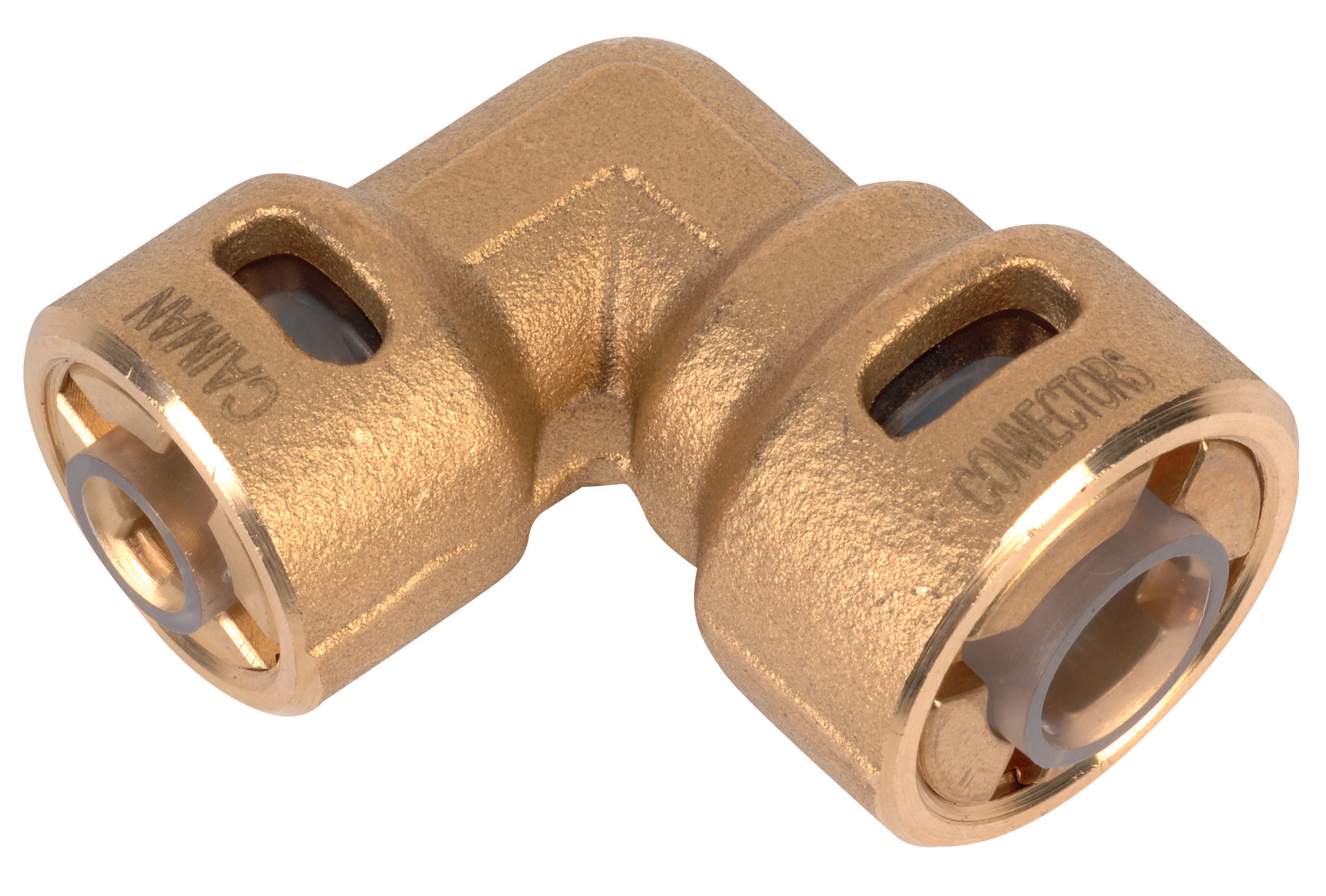
Pressure reduction couplings serve as critical interface points in high-pressure systems, managing flow transitions and preventing downstream component damage. The CBM Quick Coupling 90° Pressure Reduction 1/4*3/8 exemplifies this function, providing angular flexibility and size reduction in a single integrated unit.
Key Selection Criteria for Maintenance Teams:
- Connection Thread Standards: The 1/4" male inlet to 3/8" outlet configuration accommodates legacy system retrofits and new installations. Verify BSPT (British Standard Pipe Taper) specifications match your existing manifold connections before ordering replacement components.
- Pressure Rating Verification: Confirm coupling pressure ratings exceed your system's maximum operating pressure by at least 25%. For systems operating at 2,000 PSI, specify couplings rated for 2,500+ PSI minimum to provide safety margin during pressure spikes or transient events.
- Leakage Prevention: 90° angled designs reduce stress concentrations at connection points compared to straight couplings. This geometry minimizes micro-movements that cause seal degradation over extended operating periods. Maintenance teams should inspect seals quarterly in systems with continuous operation.
- Material Compatibility: Verify material composition (brass, stainless steel, or composite) matches your fluid type. Aggressive cleaning solutions, hydraulic fluids, and cooling mediums require different material specifications to prevent corrosion and premature seal failure.
Spray Nozzle Selection: Matching Pressure Indices to Operational Requirements
Spray nozzles represent the precision interface where high-pressure fluid transforms into controlled spray patterns. Your nozzle selection directly determines cleaning efficiency, material removal rates, and system safety. 3G Electric's technical portfolio includes three HP flat jet nozzles with distinct pressure indices and spray angles, each engineered for specific maintenance applications.
Understanding Pressure Index Ratings:
Pressure indices (025, 055, 050) reference performance characteristics relative to standard test conditions (3,000 PSI). Higher indices indicate greater flow capacity and wider spray patterns at equivalent pressures.
Application 1: General Industrial Cleaning (Low-Flow, High-Impact)
The CBM Flat Jet Nozzle HP 1/4"M BSPT Index 055 Angle 15° operates optimally in systems requiring concentrated cleaning force with minimal fluid consumption. At 2,000 PSI, this nozzle produces a tight 15° spray pattern ideal for:
- Removing accumulated scale from heat exchanger surfaces
- Degreasing equipment in production line maintenance intervals
- Cleaning precision machine components without water damage
Maintenance teams should anticipate flow rates of 6-8 gallons per minute (GPM) at standard pressure. This lower flow rate reduces infrastructure load and suits facilities with water recirculation systems requiring minimal waste fluid handling.
Application 2: Broad-Pattern Surface Cleaning (Medium-Flow, Wide Coverage)
The CBM Flat Jet Nozzle HP 1/4"M BSPT Index 25 Angle 15° provides moderate flow capacity with controlled spray divergence. This nozzle addresses maintenance scenarios requiring area coverage without excessive pressure concentration:
- Large surface area cleaning in food processing facilities
- Vehicle and equipment exterior washing in transportation maintenance
- Building exterior maintenance where concentrated pressure creates damage risk
At equivalent pressures, index 025 nozzles deliver 20-25% higher flow volumes than index 055 specifications. Maintenance teams deploying these nozzles typically expect 10-12 GPM flow rates, requiring proportionally larger waste management infrastructure.
Application 3: Aggressive Material Removal (Maximum-Flow, Steep-Angle Impact)
The CBM Flat Jet Nozzle HP 1/4"M BSPT Index 50 Angle 40° combines high flow capacity with aggressive 40° spray angle for maximum impact force distribution. This nozzle specification suits demanding maintenance applications:
- Concrete and pavement surface cleaning (removing embedded contaminants)
- Heavy mill scale removal from steel equipment during restoration
- Aggressive coating removal preparation before repainting or recoating
The steeper 40° angle spreads impact force across wider area compared to 15° nozzles, reducing localized material erosion while maintaining sufficient cleaning force. Maintenance teams should anticipate 15-18 GPM flow rates and implement proper pressure gauge monitoring to prevent equipment stress during extended operation.
Nozzle Installation and Maintenance Best Practices:
All CBM nozzles use 1/4" male BSPT connections requiring thread sealant (PTFE tape or equivalent) to prevent leakage. Install nozzles at final system location, minimizing intermediate connections that create additional leak points. Inspect spray pattern integrity weekly—clogging or asymmetrical pattern indicates mineral buildup or erosion requiring replacement. Maintain spare nozzles onsite, as pattern degradation often occurs unexpectedly during critical cleaning operations.
System Integration: Coupling, Nozzle, and Mounting Configuration
Successful high-pressure system deployment requires integrated design where pressure reduction, nozzle selection, and structural mounting operate as coordinated subsystems. Maintenance teams implementing 3G Electric components must understand these integration requirements.
Mounting Structure and Vibration Control
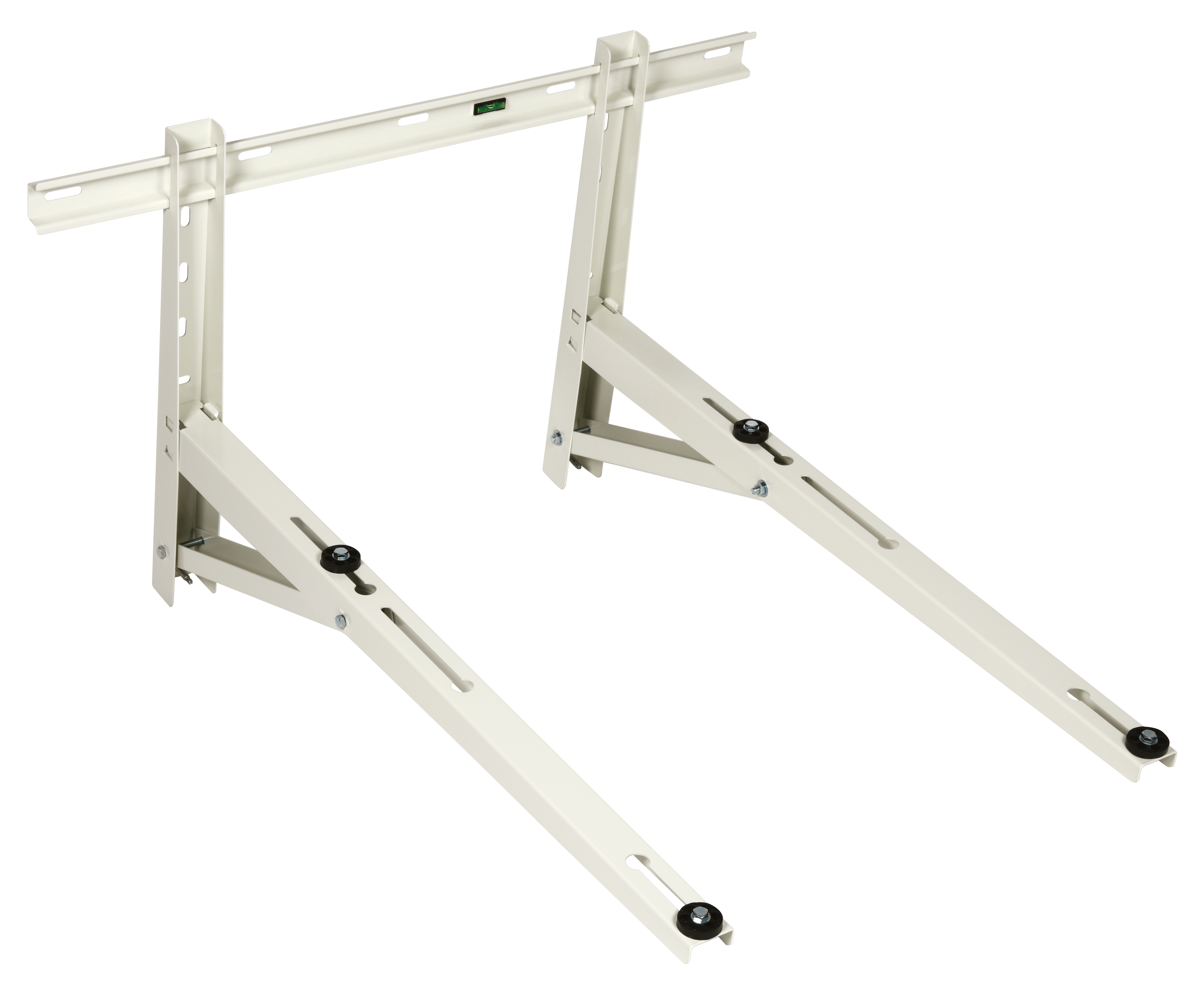
The CBM Wall Bracket 1000 provides structural mounting for pressure reduction systems, nozzle manifolds, and fluid delivery hoses. Proper mounting eliminates vibration-induced stress that accelerates seal failure and reduces system lifespan. Key maintenance considerations:
- Load Rating Verification: The 1000-series bracket accommodates manifold assemblies up to 1,000 pounds (450 kg). Calculate total assembly weight including fluid-filled hoses to confirm bracket capacity before installation.
- Vibration Isolation: Install elastomeric isolation pads between bracket and mounting surface, especially in facilities with reciprocating equipment or high-frequency vibration sources. This simple addition extends coupling and seal lifespan by 30-40% in industrial environments.
- Alignment Precision: Mount bracket perpendicular to primary nozzle spray pattern using precision levels and laser alignment tools. Misalignment of more than 2 degrees increases stress concentration in coupling connections, leading to micro-leakage and seal degradation.
- Accessibility for Maintenance: Position bracket installation to allow technicians unobstructed access to coupling quick-disconnect features, nozzle tips, and pressure gauge ports. Poor accessibility directly correlates with deferred maintenance and extended system downtime.
Maintenance teams must implement systematic pressure monitoring protocols. Install pressure gauges at three critical points: main supply (pressure source), coupling outlet (post-reduction), and nozzle manifold inlet (final delivery point). Pressure drop exceeding 100 PSI between consecutive monitoring points indicates leakage requiring immediate component inspection.
Common failure modes include:
- Coupling leakage: Indicates worn seals requiring replacement. Quick-disconnect design allows field replacement without full system shutdown.
- Nozzle tip clogging: Reduces effective pressure at spray pattern. Clean nozzle orifices using soft brass wire or ultrasonic cleaning equipment; avoid steel instruments that damage precision surfaces.
- Pressure oscillation: Indicates cavitation in pump discharge or air entrainment in supply fluid. Verify fluid reservoir level and pump inlet conditions before component replacement.
Maintenance Documentation and Compliance Requirements
Proper industry application deployment requires technical documentation supporting maintenance decisions. Establish component specification records including:
- Coupling pressure ratings and installation torque specifications
- Nozzle performance curves (flow vs. pressure relationships)
- Mounting hardware load ratings and vibration isolation properties
- Preventive maintenance intervals based on system duty cycle
Document all component replacements with dates, technician identifications, and performance changes observed post-installation. This historical data identifies patterns suggesting systemic issues (e.g., recurring seal failures indicating elevated supply fluid temperatures or contamination).
3G Electric's 35+ years in industrial equipment distribution reflects our understanding that Industry Applications success depends on maintenance team knowledge, proper component selection, and disciplined execution of service protocols. Engage our technical support team when deploying pressure systems in novel applications or when system performance degrades unexpectedly.