Introduction to Burner System Maintenance & Service
Industrial burner systems are critical components in manufacturing, processing, and heating applications worldwide. The Maintenance & Service of these systems requires a systematic approach that balances preventive care with responsive repairs. With over 35 years of experience distributing industrial equipment globally, 3G Electric has supported thousands of maintenance teams in optimizing burner performance and reliability.
Burner systems operate under demanding conditions—high temperatures, variable fuel pressures, and continuous cycling. Without proper Maintenance & Service protocols, you risk efficiency losses, increased emissions, safety hazards, and unexpected equipment failures. This guide provides actionable procedures that maintenance teams can implement immediately to improve system reliability and operational costs.
Section 1: Pre-Season Inspections and Component Assessment
Visual Inspection Protocol
Before the heating or processing season begins, conduct a comprehensive visual inspection of your burner system. Start with the external housing and work systematically through each component. Look for signs of corrosion, discoloration, fuel leaks, or structural damage. Pay particular attention to connection points, gaskets, and seals where deterioration commonly occurs.
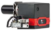
For modulating burner systems like the FBR BURNER GAS X5/MF TL EL VC LPG, inspect the die-cast aluminum body for cracks or casting defects that could compromise performance or safety. Check that the high-pressure fan assembly rotates freely and shows no signs of bearing wear. Verify all electrical connections are secure and corrosion-free, especially critical for systems with optional PID modulation kits and temperature probes.
Critical Component Testing
Examine your fuel nozzles with particular care. Flat jet nozzles like the CBM Flat jet nozzle HP 1/4"M BSPT index 25 angle 15° and the CBM Flat jet nozzle HP 1/4"M BSPT index 055 angle 15° must deliver fuel atomization at precise spray angles. Remove nozzles carefully and inspect the tip for carbon buildup, erosion, or dimensional wear. Even minor dimensional changes affect fuel distribution and combustion efficiency. Clean nozzles using appropriate solvents—never use mechanical tools that could damage the precision-machined orifice.
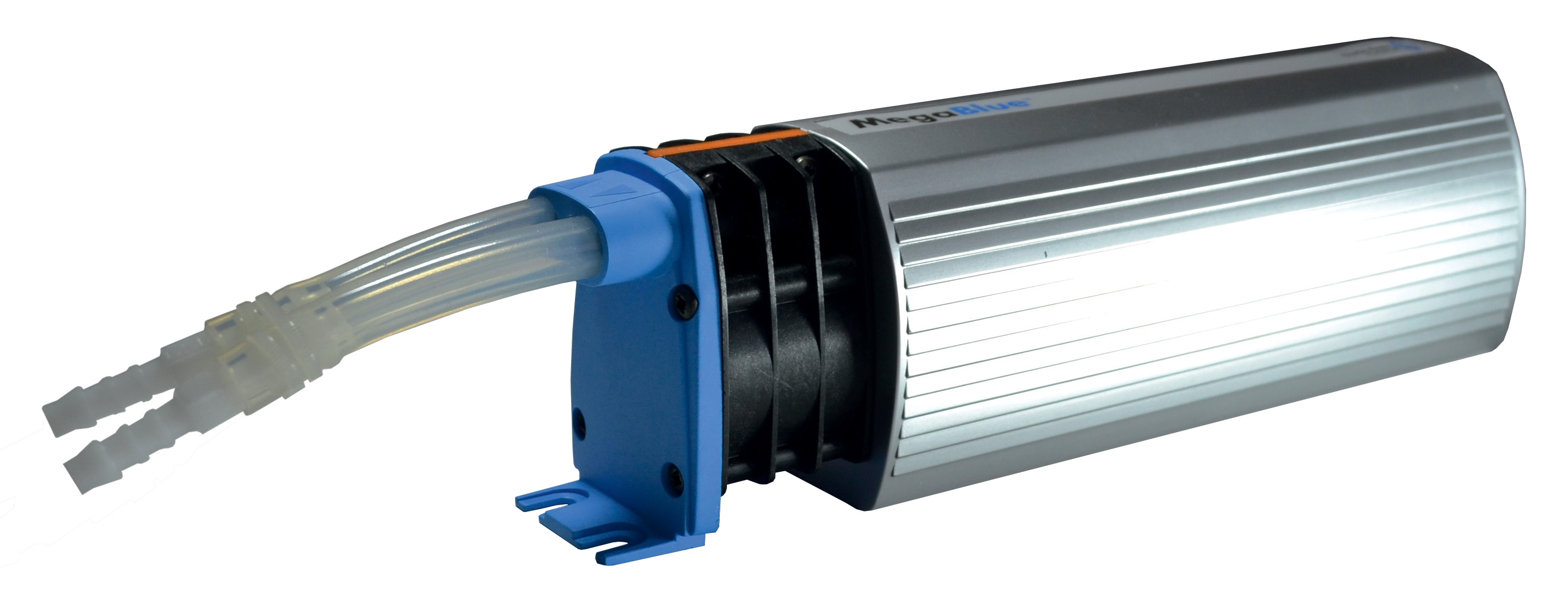
Test all pressure gauges and safety devices. Your alarm and shut-off systems, such as the CBM Megablue reservoir alarm + shut-off X87-813, must respond accurately to pressure changes. Verify that alarm thresholds trigger at specified pressure points and that shut-off mechanisms operate smoothly. Document all readings and compare them to baseline measurements from previous seasons.
Expansion Tank and Pressure System Checks
The expansion tank is often overlooked during routine maintenance, yet it plays a vital role in system stability. Use the CBM Expansion tank inflator battery 2000 mAH to check and adjust pre-charge pressure in diaphragm-type expansion tanks. Proper pre-charge pressure prevents pulsing, reduces component stress, and extends tank life.
Measure pre-charge pressure when the system is cool and depressurized. The pre-charge should typically be 0.9 times the minimum system operating pressure. For systems operating at 1.5 bar, set pre-charge to approximately 1.35 bar. If pre-charge is low, use the battery-powered inflator to add air to the tank's air valve. This simple procedure, performed annually, prevents many common pressure-related failures and improves system responsiveness.
Section 2: Cleaning and Combustion Optimization
Fuel Supply System Cleaning
Contamination in fuel supply lines undermines burner performance and reduces nozzle life. Disconnect fuel supply lines and flush the system with clean fuel or appropriate solvents. Check fuel filters and strainers for debris accumulation. Replace filters if they show significant discoloration or blockage—restricted fuel flow forces nozzles to operate outside design specifications.
Inspect fuel line hoses for internal deterioration. Fuel can break down hoses from inside, creating particulates that clog nozzles. If you notice fuel color change, unusual odor, or visible sediment, drain and replace the fuel. Store replacement fuel in clean, sealed containers away from water and contaminants.
Combustion Air System Maintenance
Clean the burner's combustion air intake and fan assembly. Dust, debris, and environmental contaminants accumulate on fan blades and impellers, reducing airflow and combustion efficiency. Use compressed air to blow out accumulated dust from fan housings and intake screens. For systems with air filters, inspect and replace filters according to environmental conditions—more frequent replacement is necessary in dusty or industrial environments.
Verify that the high-pressure fan assembly (critical in modulating systems) operates at full capacity. Listen for unusual noise or vibration that could indicate bearing wear. If the fan speed seems reduced or inconsistent, measure actual airflow with an anemometer if possible. Low airflow impacts combustion quality, increases emissions, and stresses the burner controller.
Nozzle Cleaning and Re-installation
Remove and thoroughly clean fuel nozzles using appropriate cleaning procedures. Soak nozzles in clean solvent for 15-30 minutes to dissolve carbon deposits. Use a soft brush to gently remove loosened deposits, then rinse thoroughly with fresh solvent. Never use metal tools or harsh abrasives that damage the precision-manufactured orifice surfaces.
Inspect the nozzle tip under magnification if available. The spray pattern should be uniform with no visible erosion or dimensional irregularity. Replace nozzles showing wear, as the cost of replacement is minimal compared to combustion inefficiency and increased emissions. When reinstalling nozzles, ensure proper seating and correct torque—over-tightening can damage the tip, while under-tightening causes fuel leaks.
After cleaning and reinstallation, run a combustion analysis test if your facility has the equipment. Measure CO, CO₂, O₂, and flue gas temperature. These measurements confirm that your cleaned system operates at design efficiency and helps establish baseline data for future comparisons.
Section 3: Safety System Testing and Documentation
Pressure and Temperature Monitoring
Test all monitoring devices that protect your system from unsafe operating conditions. The CBM Megablue reservoir alarm + shut-off system must respond reliably to overpressure conditions. With the system running, gradually increase pressure (or simulate pressure increase if available) and verify that the alarm triggers at the set point. Confirm that the shut-off valve closes completely when alarm conditions are met.
Document all pressure readings at minimum, typical, and maximum operating conditions. Create a baseline chart showing normal operating pressures throughout the heating or processing cycle. This baseline becomes your reference for identifying future problems—significant deviations from baseline readings often indicate emerging issues before catastrophic failure occurs.
Modulation System Verification (PID Equipped Systems)
For burners equipped with optional PID modulation kits, verify that the system responds proportionally to load changes. The burner should smoothly increase and decrease output as demand fluctuates. Jerky or hesitant modulation indicates sensor drift, control module issues, or fuel pressure instability.
If your system has a temperature probe, remove and inspect it for scale buildup or corrosion. Clean the probe surface carefully with appropriate solvents. Recalibrate the probe according to manufacturer specifications. Even small sensor inaccuracies compound over time, causing the control system to maintain improper fuel-air ratios.
Electrical and Safety Interlock Testing
Test all electrical interlocks and safety switches. Verify that the burner will not start if the combustion air fan fails to reach operating speed. Confirm that flame detection systems (if present) properly recognize combustion within 1-2 seconds of ignition. Ensure that the burner shuts down immediately if flame is lost during operation.
Inspect all electrical connections and wiring for corrosion, loose terminals, or damaged insulation. Vibration and thermal cycling gradually loosen connections, reducing reliability and creating fire hazards. Tighten all terminals and consider applying dielectric grease to prevent future corrosion.
Section 4: Troubleshooting Common Issues and Creating Maintenance Records
Identifying Combustion Problems
Poor combustion manifests as incomplete burning, excessive smoke, or unusual odor. Start by reviewing your combustion analysis data—if CO levels are elevated, the fuel-air ratio is too rich (excess fuel). If O₂ levels are very high and CO₂ is low, combustion is too lean (excess air). Adjust the fuel pressure or air/fuel ratio controls to bring measurements back to specification.
If combustion remains problematic after adjustments, suspect nozzle issues. A worn or damaged nozzle cannot atomize fuel properly, creating large droplets that resist combustion. Clogs in nozzle orifices prevent normal spray pattern formation. Replace the nozzle and retest before making further adjustments.
Pressure System Issues
Fluctuating system pressure indicates problems in the expansion tank, pump, or pressure regulation. Low pre-charge pressure in the expansion tank causes pulsing and instability. Use the CBM Expansion tank inflator battery 2000 mAH to check and restore proper pre-charge pressure. If pressure continues fluctuating after pre-charge adjustment, the tank diaphragm may be ruptured—replacement becomes necessary.
Continuously rising pressure suggests a failing pressure relief valve. Relief valves should open smoothly at set pressure and close tightly when pressure drops. If a relief valve sticks open or fails to hold pressure, replacement is required. Never attempt to disassemble or adjust relief valves without proper training—they are calibrated at the factory for safe operation.
Documenting Maintenance Activities
Maintain detailed records of all Maintenance & Service activities. Record inspection dates, findings, repairs performed, parts replaced, and any adjustments made. Include combustion analysis results, pressure readings, and temperature measurements. Over time, these records reveal patterns—recurring problems point to underlying causes that require systemic solutions rather than repeated repairs.
Create a seasonal maintenance checklist that your team follows consistently. Include specific tasks, required tools, safety precautions, and expected completion time. Assign responsibility for each task and track completion dates. This systematic approach ensures nothing is overlooked and provides accountability across your maintenance organization.
Share maintenance records with equipment manufacturers or authorized service providers if problems persist. 3G Electric's 35+ years of experience in industrial equipment distribution means our technical team can often diagnose issues from detailed maintenance records, helping you avoid unnecessary downtime.
Conclusion
Proper Maintenance & Service of industrial burner systems protects your investment, ensures safe operation, and optimizes energy efficiency. By implementing systematic inspection procedures, maintaining detailed records, and addressing issues promptly, maintenance teams worldwide reduce downtime and extend equipment lifespan significantly. The procedures outlined in this guide apply across different burner models and industrial applications—adapt them to your specific equipment and operating environment.
Contact 3G Electric for genuine replacement parts, technical guidance, or specialized equipment to support your maintenance program. With our global distribution network and deep expertise in industrial equipment, we partner with maintenance teams to keep critical systems operating reliably.