Understanding Hydraulic Component Integration Challenges
Problematic hydraulic system performance often stems from improper component integration rather than individual component failure. Procurement Engineers must understand how quick couplings, pressure reduction valves, flat jet nozzles, and mounting hardware interact within integrated systems. With over 35 years of experience distributing industrial equipment globally, 3G Electric has identified that approximately 60% of service calls relate to incompatible component specifications or incorrect assembly sequences.
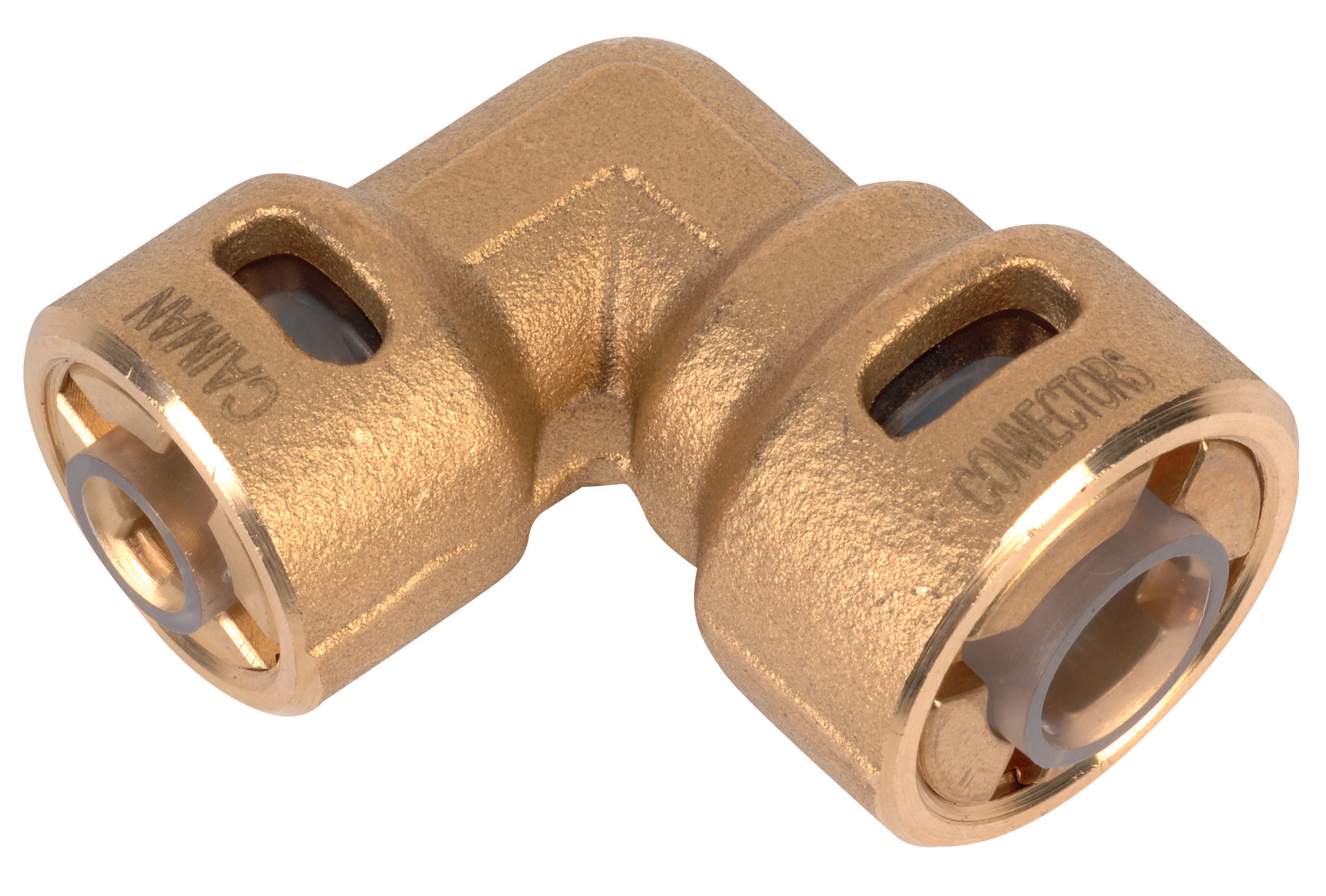
When integrating CBM Quick coupling 90° pressure reduction 1/4*3/8 units into existing hydraulic circuits, the pressure rating mismatch represents the most common failure mode. The coupling's integrated 90-degree design and pressure reduction capability require precise downstream specification matching. If your nozzle selection exceeds the coupling's reduced pressure output, system efficiency drops dramatically, and component strain accelerates wear cycles.
The integration challenge extends beyond pressure compatibility. Flow rate calculations must account for the coupling's internal geometry and the cumulative pressure drop across all components in series. A procurement strategy that treats each component independently inevitably creates bottleneck conditions where one undersized component cascades performance degradation across the entire hydraulic circuit.
Diagnosing Nozzle Selection and Flow Rate Mismatches
Flat jet nozzles demand precise matching to your system's pressure profile and application requirements. The index rating directly correlates to orifice size and flow capacity, making incorrect selection a primary cause of under-performance.
Common Nozzle Integration Errors:
- Index Specification Mismatch: Using CBM Flat jet nozzle HP 1/4"M BSPT index 055 angle 15° in applications designed for CBM Flat jet nozzle HP 1/4"M BSPT index 25 angle 15° reduces effective spray coverage by 45-50%, leading to incomplete cleaning or cooling cycles
- Angle Incompatibility: Selecting CBM Flat jet nozzle HP 1/4"M BSPT index 50 angle 40° for precision applications requiring 15-degree deflection creates overspray and pressure drop inefficiencies
- Connection Thread Verification: Confirming 1/4"M BSPT compatibility before procurement prevents costly on-site adapter requirements
To diagnose nozzle integration issues, measure system pressure at three critical points: upstream of the coupling, immediately downstream of the coupling, and at the nozzle inlet. Expected pressure loss across a properly integrated coupling ranges from 2-4 bar under nominal flow conditions. Pressure drops exceeding 6 bar indicate either a clogged nozzle, incorrect index specification, or upstream coupling degradation.
Flow rate verification requires calculating the theoretical flow based on your pump displacement and operating RPM, then comparing actual system output using calibrated flow meters. If actual flow measures 15% below theoretical capacity, suspect accumulated restrictions across multiple components rather than a single failure point. This diagnostic approach guides targeted maintenance rather than unnecessary component replacement.
Mechanical Mounting and Installation Integration
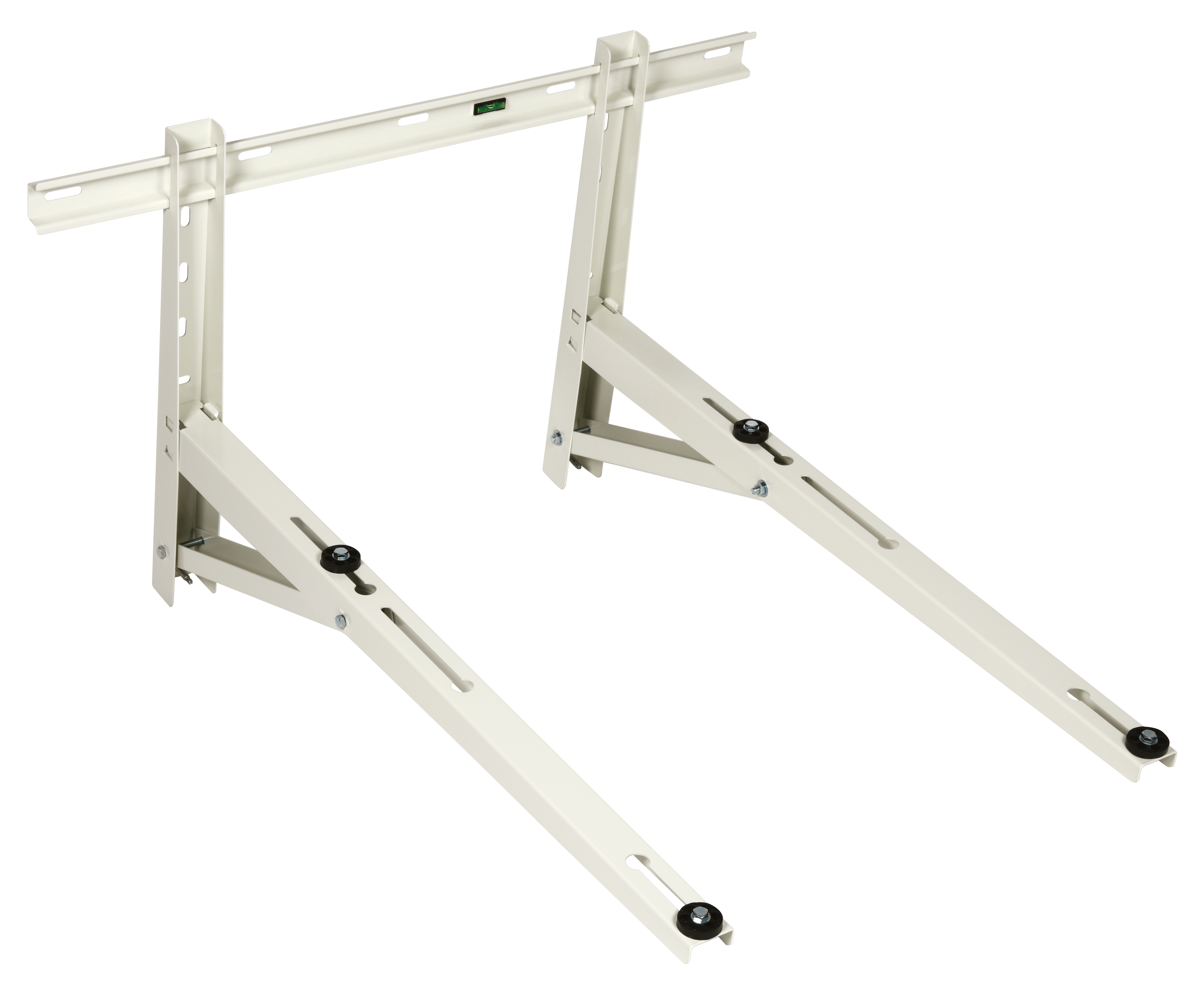
Hydraulic system reliability depends critically on mechanical stability, a factor frequently overlooked during procurement planning. The CBM Wall bracket 1000 represents standard mounting infrastructure, yet improper installation creates vibration, misalignment, and accelerated component fatigue.
Mounting Integration Checklist:
- Wall Surface Assessment: Verify structural capacity before installing brackets; insufficient support causes micro-movements that stress coupling threads and nozzle connections
- Vibration Isolation: Implement elastomer or spring isolation between bracket and wall to attenuate pump pulsations, reducing stress on quick coupling connections by 30-40%
- Alignment Verification: Use dial indicators to confirm ±0.5mm concentricity between pump discharge and nozzle inlet; misalignment exceeding 1mm introduces asymmetrical loading on coupling threads
- Component Spacing: Maintain minimum 50mm clearance from bracket to nozzle spray pattern, preventing backpressure accumulation and reducing effective nozzle performance
From 3G Electric's extensive field experience, brackets installed without vibration isolation show 3-4x higher connector wear rates compared to properly isolated installations. The initial cost of vibration isolation hardware ($150-300 per installation) prevents coupling replacement expenses exceeding $800-1200 within 18-24 months.
Threaded connections within the mounting assembly require periodic verification. Quarterly inspections using calibrated torque wrenches ensure coupling threads maintain proper clamping force. Common specifications demand 25-35 Nm for 1/4" BSPT connections, with variations depending on material composition. Over-tightening (>40 Nm) initiates thread stripping; under-tightening (<20 Nm) permits micro-movements that gradually loosen connections.
Preventive Maintenance Protocols and Performance Monitoring
Effective Maintenance & Service programs transition from reactive troubleshooting to predictive monitoring. 3G Electric's 35+ years of global distribution experience demonstrates that systematic preventive maintenance reduces unplanned downtime by 65-75% and extends component lifespan by 40-50%.
Systematic Maintenance Schedule:
Weekly Inspections:
- Visual examination of coupling connection points for seepage or discoloration
- Pressure gauge verification at coupling inlet and outlet
- Nozzle spray pattern assessment for asymmetry or degradation
- Bracket fastener tightness verification using calibrated torque wrench
- Fluid sample collection and laboratory analysis (viscosity, contamination, oxidation)
- Flow rate measurement comparing current output to baseline specifications
- Thermal imaging of coupling and nozzle connection points; localized hotspots indicate excessive friction or pressure drop
- Documentation of pressure readings under standard operating load conditions
- Systematic replacement of quick coupling seals every 12 months or 2000 operational hours
- Nozzle cleaning using non-abrasive methods; ultrasonic cleaning removes internal mineral deposits without dimensional distortion
- Bracket fastener replacement with stainless steel hardware if corrosion initiation appears
- System pressure trending analysis; pressure increasing >5% monthly indicates internal coupling degradation
Problematic component integration frequently becomes apparent through fluid analysis rather than visual inspection. Elevated copper or iron content in hydraulic fluid suggests accelerated coupling wear from misalignment or vibration. Increased acid number (TAN) indicates oxidative stress, often resulting from excessive pressure drop and heat generation at nozzle orifices.
Procurement Engineers should establish baseline performance metrics during initial system commissioning: nominal pressure at each coupling, standard flow rate at specified nozzle, and expected power consumption. Monthly comparisons identify degradation trends before failures occur. Systems showing 2-3% monthly performance degradation typically require component replacement within 4-6 weeks; systems with stable metrics support extended service intervals.
Implementing condition-based monitoring reduces inventory holding costs by 25-30% through optimized spare parts procurement. Instead of maintaining large quantities of couplings, nozzles, and brackets, predictive data guides procurement timing, ensuring replacement components arrive precisely when needed rather than accumulating unnecessary stock.
Integration Troubleshooting Decision Tree
When encountering hydraulic system performance issues, systematic diagnosis prevents inappropriate replacement of functional components:
1. Pressure Performance Degradation → Measure pressure at coupling inlet/outlet; if drop exceeds 6 bar, inspect coupling seals and internal geometry; if pressure remains correct, diagnose downstream nozzle index mismatch
2. Flow Rate Reduction → Compare actual flow to baseline; if reduction <10%, verify nozzle cleanliness; if reduction 10-20%, suspect coupling internal degradation; if reduction >20%, verify pump displacement and operating RPM
3. Spray Pattern Asymmetry → Inspect nozzle orifice for debris; if orifice appears clear, verify coupling alignment and bracket mechanical stability; misalignment >1mm typically causes asymmetrical spray
4. Thermal Hotspots → Locate highest temperature point using thermal imaging; if hottest point is at coupling, suspect pressure drop and verify coupling specification compatibility; if hottest point is at nozzle, verify index rating matches application requirements
5. Vibration or Noise → Inspect bracket installation and fastener tightness; apply vibration isolation; retest after isolation implementation
This systematic approach conserves procurement budget by targeting specific problems rather than replacing entire component assemblies. Documentation of troubleshooting results builds institutional knowledge that improves future procurement specifications and maintenance planning.