Understanding Industry Applications: Hydraulic Couplings and Nozzle Systems
Hydraulic couplings and precision spray nozzles are critical components in countless industry applications—from high-pressure cleaning systems and agricultural equipment to industrial burners and manufacturing processes. When these systems fail, production stops and costs escalate rapidly. Over 35 years, 3G Electric has supported maintenance teams worldwide in diagnosing and resolving hydraulic coupling and nozzle failures across diverse applications.
This troubleshooting guide focuses on the two most common failure modes: inadequate pressure delivery at the nozzle and spray pattern degradation. Unlike general pressure system guides, this article addresses the specific interface between couplings and nozzles, where most industry application problems originate.
Section 1: Diagnosing Pressure Loss at Quick Couplings
Common Pressure Loss Scenarios
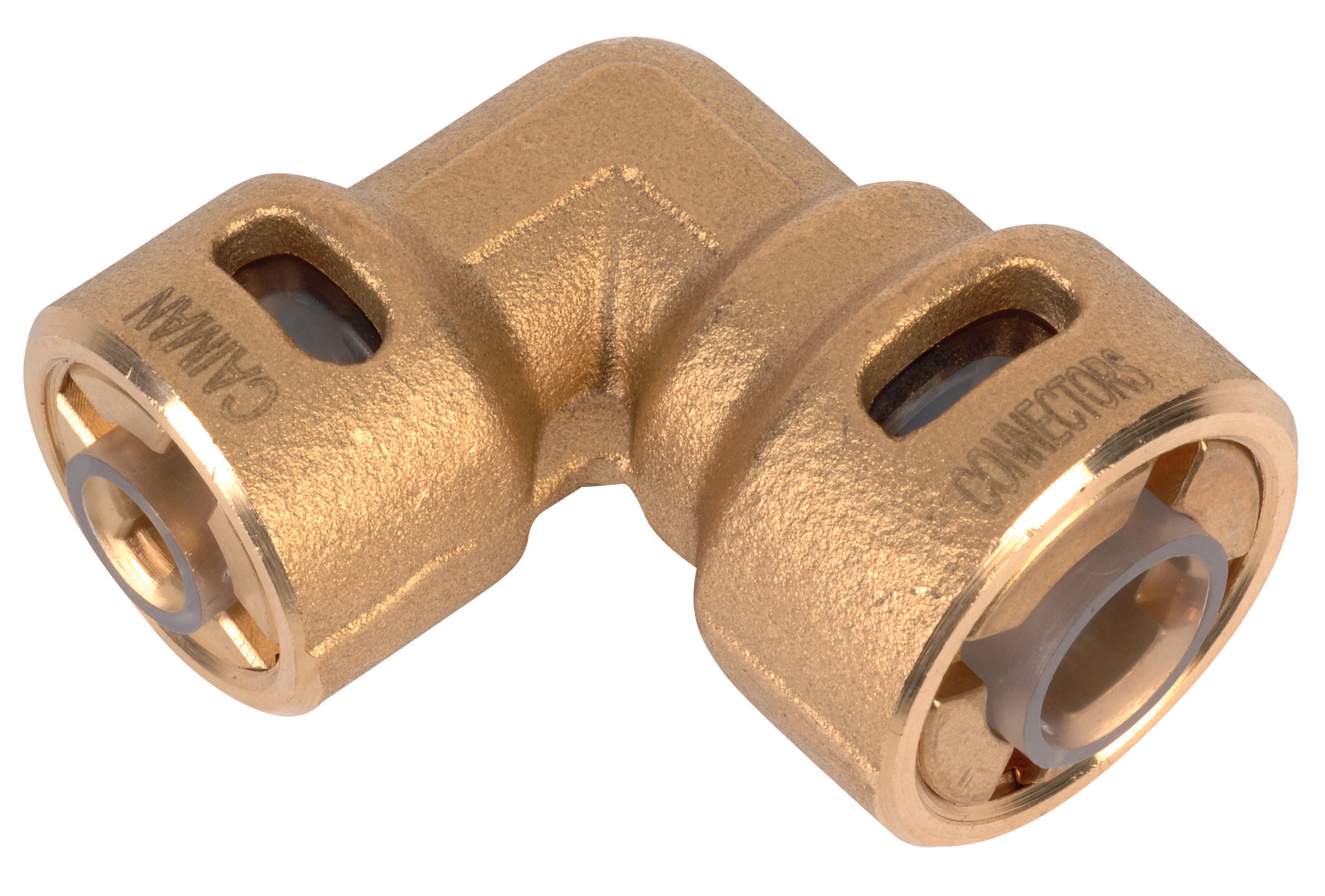
Quick couplings like the CBM Quick Coupling 90° Pressure Reduction 1/4*3/8 are engineered to maintain system pressure while allowing rapid connection and disconnection. However, they represent potential leak points when maintenance teams overlook critical diagnostics.
Step 1: Establish baseline pressure. Before troubleshooting, record the system's operating pressure at three points: upstream of the coupling, immediately downstream, and at the nozzle inlet. A significant drop across the coupling (more than 5-10 bar, depending on system design) indicates internal leakage.
Step 2: Inspect physical condition. Disconnect the coupling at a maintenance interval and visually inspect:
- Socket and plug for scoring, pitting, or corrosion
- Seals (typically EPDM or nitrile) for cracks, hardening, or extrusion
- Pressure relief valve function (many couplings include built-in relief mechanisms)
- Seal degradation from temperature cycling
- Micro-leakage through the check valve
- Worn poppet mechanisms
Pressure Reduction Across Couplings: When It's By Design
Maintenance teams often misinterpret the pressure drop across a reduction coupling as a malfunction. The CBM Quick Coupling 90° Pressure Reduction 1/4*3/8 intentionally reduces pressure from 1/4" inlet to 3/8" outlet connection. This design serves industry applications where:
- High-pressure supply lines operate at 280+ bar
- Downstream components (like spray nozzles) are rated for lower pressures (typically 100-200 bar)
- Direct connection would cause component failure or unsafe operation
Verify your coupling matches your application's pressure requirements. Measure pressure drop across a known-good coupling under typical operating conditions. Any excessive drop beyond the designed reduction indicates wear.
Section 2: Spray Nozzle Performance Troubleshooting
Diagnosing Spray Pattern Degradation
Spray nozzles are precision-engineered components that perform reliably only within specific pressure and flow parameters. The most common complaint from maintenance teams is spray pattern change—narrowing, widening, or asymmetry that degrades process quality.
Flat jet nozzles like the CBM Flat Jet Nozzle HP 1/4"M BSPT Index 25 Angle 15° and CBM Flat Jet Nozzle HP 1/4"M BSPT Index 055 Angle 15° are particularly sensitive to backpressure and inlet turbulence. They produce a thin, flat spray pattern essential for:
- Uniform coating applications
- Cooling or cleaning processes requiring precise coverage
- High-flow, low-pressure systems
1. Establish baseline conditions. Document spray pattern under normal operating pressure using photo or video evidence. Include angle width, spray uniformity, and droplet distribution characteristics.
2. Monitor inlet pressure and flow rate. Many maintenance teams focus only on pressure but neglect flow. Restricted flow (from blocked screens or filters upstream) causes turbulent inlet conditions that distort flat jet patterns. Use a flow meter if available, or measure system pressure while monitoring output.
3. Isolate the nozzle. Remove the nozzle and inspect the orifice plate under magnification (10x or higher). Look for:
- Erosion around the orifice (pitting or roughness)
- Mineral deposits or varnish buildup
- Debris or fiber blockage
4. Clean or replace. For mineral deposits, soak nozzles in a solvent appropriate to your fluid type (mineral oil system = mineral oil-compatible solvent; water-based system = water and mild detergent). Never use abrasive scrubbing or wire brushes—this damages the precision orifice.
5. Verify replacement nozzle index. This is critical. The index number (25, 055, 50, etc.) indicates orifice size. Installing an incorrect index creates obvious spray pattern mismatch. The CBM Flat Jet Nozzle HP 1/4"M BSPT Index 50 Angle 40° handles double the flow of the index 25 version while maintaining spray angle. Refer to your equipment documentation for correct replacement index.
High-Pressure Nozzle Considerations
The "HP" designation on these CBM nozzles indicates high-pressure rating (typically 200+ bar). Maintenance teams sometimes confuse this with minimum required pressure. These nozzles will operate at lower pressures, but flow rate changes predictably—approximately proportional to the square root of pressure. If your spray coverage suddenly decreases, check whether system pressure has dropped before assuming nozzle failure.
Section 3: System Integration and Installation Troubleshooting
Mounting and Bracket Issues
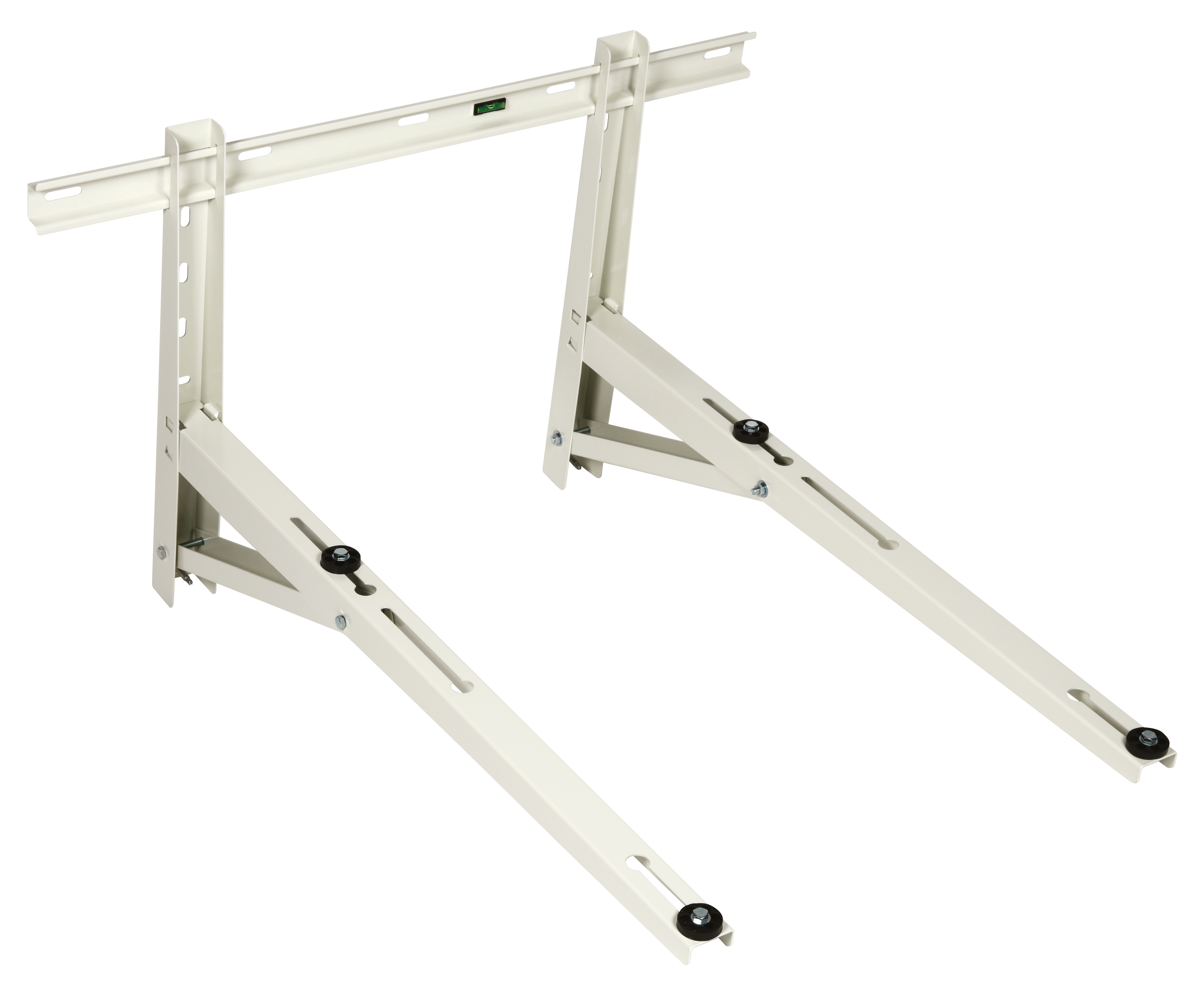
Even properly functioning couplings and nozzles perform poorly if improperly mounted. The CBM Wall Bracket 1000 and similar mounting solutions deserve maintenance attention beyond simple installation.
Common mounting failures in industry applications:
- Vibration-induced fitting rotation. Wall brackets must be rated for the weight and vibration of your specific equipment. An undersized bracket allows the nozzle assembly to rotate on its own threads, gradually loosening connections. The CBM Wall Bracket 1000 is engineered for specific load capacities—verify your installation doesn't exceed these limits.
- Hose whipping and coupling separation. When high-pressure hydraulic systems operate, hoses can whip if not properly supported. Maintenance teams must install support brackets at intervals (typically 1-2 meters) to prevent hose movement. Unsupported hose sections cause lateral stress on quick couplings, leading to premature seal wear.
- Thermal expansion in industry applications. Temperature cycling causes both hose and metal fittings to expand and contract. Over months of operation, this loosens NPT (pipe thread) connections. Inspect threaded connections quarterly in high-temperature applications. Re-tighten with the correct torque wrench setting—over-tightening crushes seals; under-tightening allows weeping leaks.
Pressure Gauge Installation for Accurate Diagnostics
Instal pressure gauges at three critical points: upstream of the coupling, downstream of the coupling, and at the nozzle inlet. Use quick-disconnect fittings matching your coupling system for safe, repeatable measurements. This three-point pressure strategy immediately identifies whether pressure loss occurs at the coupling, in the hose run, or at the nozzle itself.
Section 4: Preventive Maintenance Strategies for Global Operations
Fluid Condition Management
Hydraulic couplings and nozzles fail prematurely when system fluids are contaminated. Maintenance teams managing multiple facilities or global equipment fleets should implement these practices:
Fluid analysis intervals. Change hydraulic fluid according to manufacturer recommendations, typically every 2,000 operating hours or annually—whichever comes first. In dusty or contaminated environments (food processing, grain handling, etc.), reduce intervals to 1,000 hours. Track fluid condition via particle count testing if your operation justifies the cost.
Filter maintenance. Hydraulic system filters protect couplings and nozzles by removing particles larger than 10 microns. Maintenance teams often change filters on fixed schedules without monitoring pressure drop across the filter element. A clogged filter restricts flow and creates backpressure conditions that cause coupling damage and nozzle pattern distortion. Install pressure switches on filters to alert operators when replacement is needed.
Water removal. Hydraulic fluids absorb moisture from humid environments or water-wash operations. Water in the system causes corrosion inside couplings and scoring of orifice plates in nozzles. Use desiccant breathers on reservoir fill caps to prevent moisture ingress. If water contamination is detected via fluid analysis, perform a complete fluid flush and replace all components that contacted the contaminated fluid.
Documentation and Failure Analysis
Over 35 years, 3G Electric has observed that maintenance teams with comprehensive equipment documentation experience 40% fewer repeat failures. For each installed coupling and nozzle system, maintain records including:
- Original installation date and equipment serial number
- Coupling model, serial number, and pressure rating
- Nozzle index, angle, and flow rating
- Inlet pressure and flow rate under normal operation
- Replacement dates and reasons (planned maintenance vs. failure)
- Photo documentation of spray patterns or pressure readings
When failures occur, conduct root cause analysis before replacing components. Document the failure mode—internal seal leakage vs. external weeping vs. catastrophic rupture. This pattern analysis helps you anticipate and prevent similar failures across your equipment fleet.
Global Supply Chain Considerations
Maintenance teams managing equipment across multiple countries should understand that hydraulic component availability varies. The CBM Quick Coupling 90° Pressure Reduction 1/4*3/8, CBM Flat Jet Nozzle HP 1/4"M BSPT Index 25 Angle 15°, CBM Flat Jet Nozzle HP 1/4"M BSPT Index 055 Angle 15°, and CBM Flat Jet Nozzle HP 1/4"M BSPT Index 50 Angle 40° are stocked globally through 3G Electric's distribution network, enabling rapid replacement without international shipping delays.
Establish spare parts inventory based on:
- Equipment criticality (mission-critical systems warrant higher spare quantities)
- Average failure intervals from your historical documentation
- Lead times from your regional distributor
- Seasonal demand (e.g., agricultural applications peak during harvest)
Maintenance teams operating in regions with limited local hydraulic expertise benefit from keeping printed technical documentation and spare coupling seals on-site. Many coupling failures can be resolved with seal replacement in 30 minutes if proper tools and documentation are available.