Controls & Safety: Field Troubleshooting Framework for HVAC Contractors
Controls & Safety systems form the backbone of reliable HVAC operations, but even well-designed installations encounter performance issues that demand systematic diagnosis. As an experienced industrial equipment distributor serving Singapore's HVAC sector for 35+ years, 3G Electric has supported thousands of contractors through complex control failures and safety system challenges.
Effective troubleshooting begins with understanding your system's diagnostic hierarchy. Before assuming component failure, verify electrical supply stability, signal continuity, and sensor calibration. Most performance degradation stems from installation issues, environmental contamination, or maintenance gaps rather than inherent component defects. This guide provides practical protocols you can implement on-site to quickly identify problems and restore system performance.
Diagnostic Testing Protocols for Pressure Switches and Safety Interlocks
Pressure switches like the Kromschroder DG 50U/6 form critical safety interlocks in burner control sequences. When burner ignition fails or safety shutdowns occur unexpectedly, systematic pressure switch testing isolates the root cause.
Testing Pressure Switch Response:
Start with visual inspection—check for physical damage, corrosion, or moisture ingress at the electrical connection. The Kromschroder DG 50U/6 meets SIL 3 and Performance Level e standards, but environmental degradation compromises its safety rating. If the switch housing shows condensation or salt deposits (common in Singapore's coastal climate), clean with dry compressed air before electrical testing.
Next, measure static pressure at the switch inlet using a precision manometer. Document the pressure reading and compare against the switch's calibrated setpoint. The DG 50U/6 features adjustable deadband settings—verify your installation uses the correct configuration for your burner type. If pressure readings drift from specification, the sensing line may contain blockages. Disconnect the tubing at both ends, flush with clean compressed air, and retest. Never use compressed air above 3 bar as excessive pressure damages the internal diaphragm.
For functional verification, apply controlled pressure through a hand pump while monitoring electrical continuity with a multimeter. The switch should activate at the factory-set pressure and deactivate within the deadband range. If response is sluggish or delayed, internal contamination may require professional recalibration or component replacement.
Common Pressure Switch Failures in Singapore Installations:
- Corrosion at electrical terminals: High humidity and salt spray environments accelerate oxidation. Apply dielectric grease to all connections quarterly.
- Sensing line blockages: Condensation in tubing freezes at the diaphragm entrance. Install drip traps and drain moisture weekly during humid seasons.
- Setpoint drift: Vibration from compressors or fans loosens adjustment screws. Use thread-locking compound on setpoint adjustments.
- Premature valve closure: Excessive pressure spikes (water hammer effect) damage the diaphragm. Install snubbers on all pressure sensing lines.
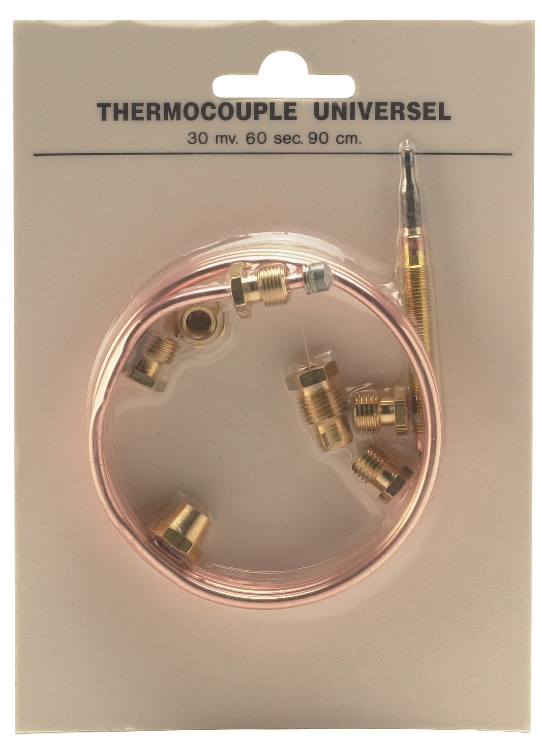
Flame Detection and Ionization Current Troubleshooting
Flame detection systems using electrode sensors and ionization relays demand precise diagnostic procedures. The Siemens QRB4A-B036B40B flame detector and CBM stainless steel electrode work together to monitor flame presence and trigger safety shutdowns when combustion fails.
Ionization Current Measurement and Analysis:
Ionization current typically ranges from 1–10 microamps depending on fuel type and electrode geometry. Use a multimeter set to DC microamps (µA) range—standard milliamp settings lack resolution for this low current. Connect the probe across the electrode sensing circuit without breaking connections; drawing current to a remote meter disrupts the control circuit. Document baseline current readings under stable flame conditions.
If ionization current falls below 1.2 µA (the Brahma Relay CE 191.4 minimum threshold), the control circuit triggers safety shutdown. Common causes include:
- Electrode fouling: Carbon, ash, or corrosion accumulation reduces ion generation. Remove the electrode and clean with a soft brass brush and acetone. Reinstall and retest within 30 minutes; readings stabilize as the electrode heats to operating temperature.
- Electrode gap misalignment: The CBM electrode must maintain correct spacing relative to the flame envelope. Measure gap using feeler gauges and adjust mounting hardware. Improper gap causes weak ionization current that fluctuates with flame intensity changes.
- High-voltage leak paths: Moisture on electrode surfaces creates unwanted current paths. Ensure electrode terminals have dry dielectric coating. In humid environments, apply silicone conformal coating to prevent condensation bridging.
- Incorrect flame characteristics: Weak or unstable flames generate insufficient ionization current. Check burner nozzle cleanliness, fuel pressure, and air intake filters. A clean burner often resolves chronic low-current faults.
The Siemens QRB4A-B036B40B connects via two-wire thermoplastic cable—verify cable continuity with a multimeter before assuming detector failure. Many false alarms trace to intermittent wire breaks at the detector connector where vibration causes micro-fractures in the cable sheath.
With burner operational, observe the control relay status. The Brahma Relay CE 191.4 energizes when flame is detected and de-energizes during flame loss. If the relay remains de-energized despite visible flame, check:
1. Sensing line obstruction: A blocked sensing port prevents proper flame monitoring. Gently blow compressed air through the detector lens and sample tube.
2. Detector lens contamination: Soot or condensation obscures the detector's infrared sensor. Remove the detector (burner off, cooled), clean the lens with lens paper and isopropyl alcohol, and reinstall.
3. Control circuit faults: Test the relay directly by applying 230V 50/60Hz power. The relay should energize immediately with an audible click.
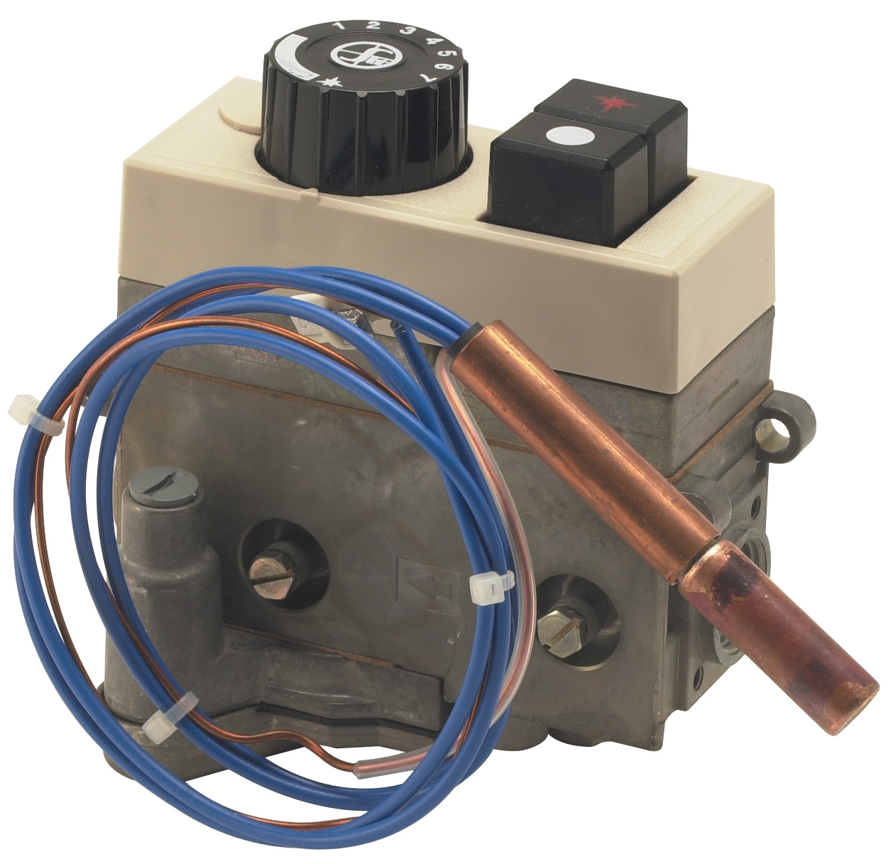
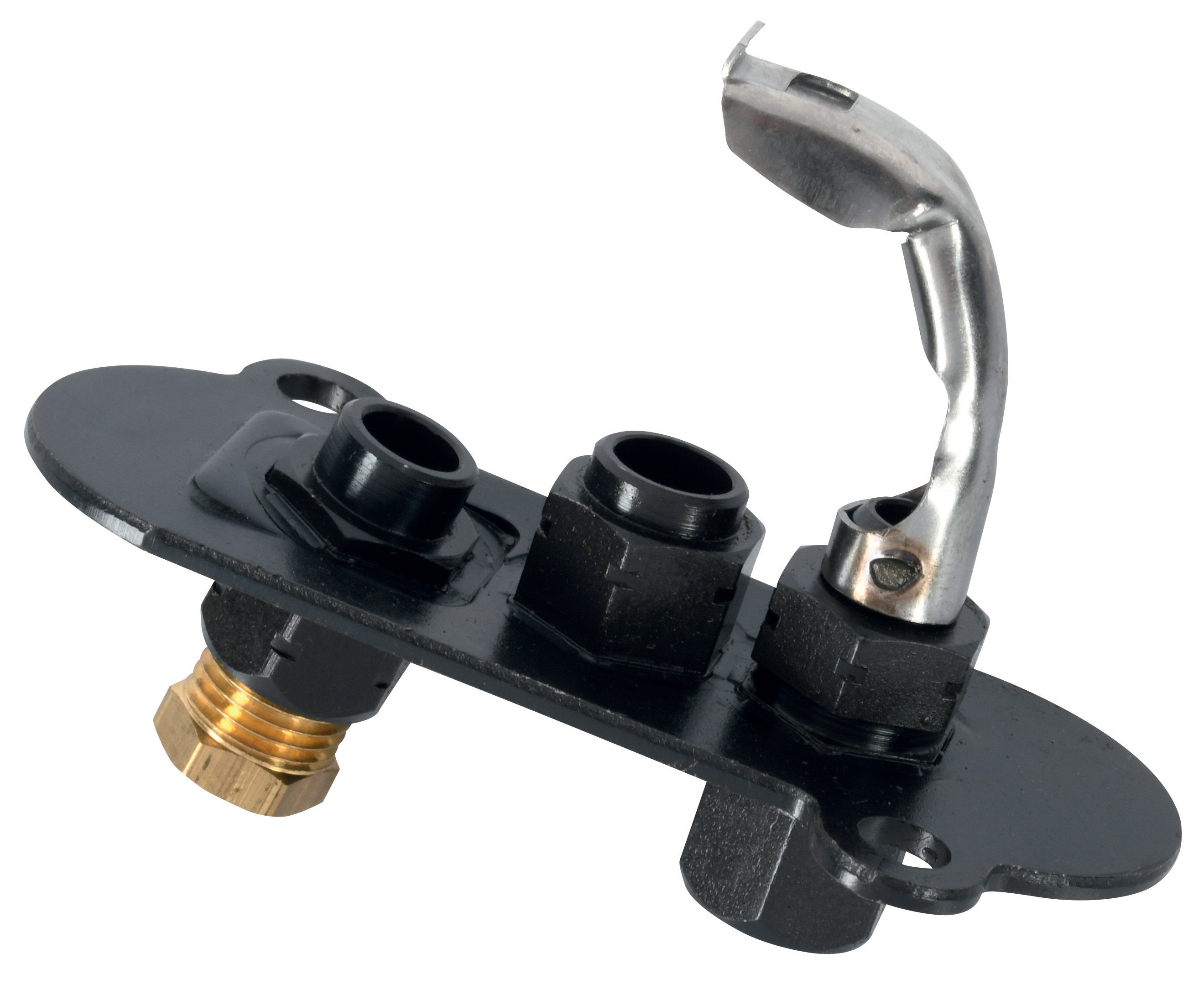
Pilot Light Systems and Ignition Circuit Optimization
The Sit universal pilot light provides reliable ignition for atmospheric and fan-assisted burners, but performance varies with maintenance and environmental conditions. Optimizing pilot light operation prevents delayed ignition, intermittent flame loss, and nuisance safety shutdowns.
Pilot Flame Assessment and Adjustment:
Observe the pilot flame characteristics during normal operation:
- Flame color: A stable blue flame indicates proper combustion. Yellow tips suggest incomplete combustion or air/fuel ratio imbalance. Orange or red flames indicate inadequate oxygen—verify air intake openings are unobstructed.
- Flame stability: The flame should remain steady when the burner cycles. Flickering or wandering flames often result from draughts or inadequate flame retention. The Sit pilot light features two flames and three positions—verify you're using the correct position for your specific application.
- Flame height: Pilot flames should touch the main burner igniter without being excessively tall. Excessive height wastes fuel and generates excessive heat on surrounding components. Adjust the pilot gas valve incrementally and retest.
When the main burner fails to ignite after pilot establishment, test the ignition circuit systematically:
1. Verify electrical continuity: With power off, disconnect the igniter electrode cable and measure resistance across the electrode tip and ground. Resistance should be less than 100 ohms. Higher resistance indicates ceramic breakdown or internal cracking—the electrode requires replacement.
2. Check ignition transformer output: Using a high-voltage probe, measure AC voltage at the electrode with the burner in ignition mode. Typical ignition transformers produce 3–5 kV AC. If voltage is absent, check transformer primary winding continuity and control circuit switching.
3. Inspect electrode positioning: The igniter electrode must be correctly positioned relative to the fuel spray pattern. Most ignition failures trace to electrode drift or mechanical loosening. Clean the electrode of any carbon deposits and ensure secure mechanical mounting.
Pilot Light Maintenance Schedule for Singapore Climate:
- Monthly: Inspect flame color and stability; clean lens if visible discoloration appears.
- Quarterly: Remove the pilot assembly and inspect burner ports for blockages; clean with a soft brass brush.
- Annually: Replace air filter elements and verify all gas connections are tight using a soap solution test.
- Biannually: Have the ignition transformer and electrode assembly professionally tested for dielectric strength.
Control Relay Integration and System Performance Optimization
The Brahma Relay CE 191.4 serves as the central decision-making component in burner control sequences, coordinating flame detection, safety interlocks, and fuel valve operation. When systems experience intermittent burner lockouts or delayed response times, relay performance optimization restores reliability.
Relay Logic Verification and Sequencing:
The Brahma relay operates on a fixed sequence: ignition attempt → flame detection monitoring → fuel valve energization → continuous flame supervision. Test each stage independently:
1. Ignition stage: Apply 230V 50/60Hz power with flame detector disconnected. The relay should energize ignition output for 4–8 seconds (adjustable depending on model). If ignition stays on continuously, the flame detection circuit is faulty.
2. Flame detection stage: With controlled flame applied to the flame detector, measure ionization current. The relay should energize main fuel valve output when current exceeds threshold (typically 1.2 µA).
3. Shutdown stage: Interrupt flame or disconnect the flame detector cable. The relay should de-energize fuel valve within 1 second and prevent immediate restart attempt (lockout safety feature).
Noise and EMI Mitigation for Relay Stability:
Electronic relays operate in electrically noisy industrial environments where variable frequency drives, motor starters, and high-voltage switching create electromagnetic interference. Install transient suppressors across inductive loads (solenoid valve coils, motor windings) and use shielded cable for all signal wiring. The Brahma Relay CE 191.4 includes internal EMI filtering, but external protection extends reliability.
- Suppress solenoid coil spikes: Install 24V DC varistor suppression modules across fuel valve solenoids. When valve de-energizes, the varistor clamps voltage spikes that otherwise couple into control circuits.
- Shield all sensor cables: Use screened cable for flame detector and pressure switch connections. Ground the cable shield at the relay chassis, not at the sensor end—this prevents ground loops.
- Isolate power circuits: Separate burner control power from lighting or motor circuits using isolated transformer windings. Many nuisance shutdowns trace to common-mode voltage rise when motors start.
After 12 months of operation, flame detection sensitivity may drift due to electrode aging or optical component oxidation. Periodic recalibration maintains safe and reliable operation:
1. With burner at steady-state, measure ionization current at the relay input terminals.
2. Compare against baseline readings documented at installation commissioning.
3. If current dropped >20%, clean electrodes and optical surfaces per the manufacturer procedure.
4. Retest and document the new baseline. If current remains low despite cleaning, schedule electrode or detector replacement before safety margin erodes further.
Practical Optimization Checklist for HVAC Control Systems
Implement this systematic review quarterly to maintain peak control system performance:
Electrical connections:
- Check all terminal blocks for loose fasteners using a properly calibrated screwdriver.
- Measure voltage at each control component input to verify supply stability (±10% of nominal).
- Clean all electrical connectors of oxidation using a dry brass brush.
- Verify pressure switch sensing lines are clear of condensation and blockages.
- Test ionization electrode current under stable flame conditions.
- Measure flame detector output signal strength if your system includes analog monitoring.
- Confirm flame detection triggers fuel valve shutdown within 1 second of flame loss.
- Test pressure switch activation at the specified setpoint ±5%.
- Verify all manual reset switches function and relays energize cleanly.
- Inspect control enclosure for moisture ingress (apply desiccant packs in humid locations).
- Verify cooling airflow around electronic components (minimum 50 mm clearance).
- Check for vibration-induced loose hardware near control mounting points.
- Inspect burner fuel lines and connections for leaks using soap solution.
- Measure fuel pressure at the control circuit inlet against specification.
- Confirm all fuel shut-off valves operate smoothly without sticking.
Leveraging 3G Electric's Controls & Safety Expertise
With 35+ years supporting Singapore's industrial equipment needs, 3G Electric maintains technical expertise across pressure switches, flame detectors, pilot lights, and control relays. When troubleshooting reveals component replacement needs, our technical team can recommend exact equivalents or superior alternatives based on your system's specific requirements and operating environment.
Contact 3G Electric's technical support to access component documentation, wiring diagrams, and calibration specifications for your control system. Our distributors maintain emergency stock of critical safety components to minimize downtime when failures occur.