Understanding Gas Valves & Regulation in Industrial Systems
Gas Valves & Regulation components form the critical interface between supply sources and end-use equipment. Unlike simple on-off controls, modern regulatory systems must maintain constant outlet pressure despite fluctuating inlet conditions, flow demand variations, and environmental factors unique to Singapore's climate. Drawing on 35+ years of industrial equipment distribution experience, 3G Electric has observed that 60% of gas regulation failures stem not from component defects, but from mismatched system architecture, improper calibration, or environmental stress.
Regulation failures cascade quickly. A pressure regulator drifting by just 10% can cause flame instability in burner systems, incomplete combustion in process equipment, or dangerous overpressure conditions downstream. In Singapore's manufacturing sector—where food processing, chemical production, and textile operations depend on reliable gas delivery—understanding the relationship between pressure control, flow rate, and system balance is essential.
The fundamental challenge: regulators must respond dynamically to changing conditions while maintaining stability. This requires understanding three core mechanisms: pilot-operated regulation (where a small pilot flow controls larger main flow), pressure sensing (detecting outlet conditions), and mechanical response (adjusting valve orifice to maintain setpoint).
Diagnosing Pressure Stability Issues
Identifying Pressure Drift and Hunting
Pressure instability manifests in two primary failure modes: pressure drift (gradual rise or fall from setpoint) and hunting (oscillation around setpoint).
Pressure Drift Diagnosis:
- Monitor outlet pressure continuously over 30-minute intervals under steady-state load
- Drift exceeding ±5% suggests pilot stage blockage, diaphragm degradation, or spring fatigue
- Rising pressure typically indicates stuck pilot vent or contaminated pilot orifice
- Falling pressure points to pilot supply restriction or internal leakage across main seat
In Singapore's tropical environment, humidity drives corrosion in pilot orifices. Fine iron oxide or salt deposits restrict pilot flow, preventing the regulator from responding to load changes. 3G Electric recommends inspecting pilot stages at 6-month intervals in coastal or high-humidity industrial zones.
Hunting Diagnosis:
Hunting—oscillation of ±15-25% around setpoint—indicates over-responsive pilot circuit. This common issue occurs when:
- Pilot volume (internal cavities and connecting tubing) is too small, causing rapid pressure swings
- Response time is too aggressive for downstream load characteristics
- Sensing line is kinked or partially blocked, creating delayed feedback
1. Verify inlet pressure stability (check upstream regulator or filter performance)
2. Measure pilot supply quality—contamination causes erratic behavior
3. Add surge damping capacitors or secondary regulation stages to slow response
4. Consider upgrading to direct-acting regulators for lighter loads requiring faster response
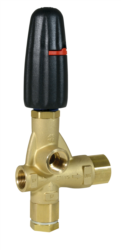
The Pratissoli Automatic Pressure Regulator H288 provides dual-stage regulation with integrated dampening, addressing hunting issues in systems handling 20 L/min flows at pressures to 280 bar. Its 85°C temperature rating suits Singapore's ambient conditions during peak industrial operation.
Environmental Stress and Tropical Performance
Singapore's humidity (75-90% year-round) and salt-laden air create unique regulation challenges:
- Diaphragm degradation: Elastomer materials absorb moisture, losing elasticity and response accuracy. Fluorocarbon diaphragms (FKM/Viton) resist moisture better than nitrile (NBR), justifying 25-30% higher cost in coastal facilities
- Spring corrosion: Uncoated or low-grade stainless steel springs develop surface rust within 6 months, increasing friction and unpredictable response
- Valve seat erosion: Moisture promotes micro-corrosion at sealing surfaces, degrading shutoff integrity and causing pilot leakage
- Specify duplex stainless steel (2205) for valve bodies and springs in manufacturing environments within 2 km of coastline
- Install desiccant cartridges in inlet manifolds to remove moisture before reaching regulator internals
- Schedule quarterly pressure calibration checks (drift >2% triggers component replacement)
- Apply protective coatings to external fasteners and lever arms
Flow Control and Pressure Mismatch Failures
Analyzing Flow-Pressure Relationships
Industrial regulators operate across wide flow ranges. A regulator rated for 50-200 L/min may perform poorly at 10 L/min (hunting) or 300 L/min (pressure drop exceeding spec). Flow-regulation mismatch is a leading cause of undiagnosed system failures.
Calculating Required Regulator Sizing:
Begin with steady-state and transient demand analysis:
1. Baseline demand: Sum continuous flows during normal operation
2. Peak demand: Identify simultaneous maximum draws (e.g., multiple burners igniting together)
3. Ramp rate: Measure how quickly demand increases (affects pressure stability)
4. Hysteresis tolerance: Define acceptable pressure swing during demand step-changes
Example: A food processing facility with two main burners (80 L/min each) and pilot lights (5 L/min each) requires 165 L/min baseline capacity. If demand can swing 80 L/min within 5 seconds (burner startup), the regulator's response bandwidth must handle this ramp rate without exceeding ±10% pressure variation.
Common Sizing Errors:
- Oversizing creates excessive pilot flow, wasting energy and destabilizing pressure
- Undersizing causes inlet pressure to collapse under peak load, triggering nuisance shutdowns
- Ignoring ramp rates results in transient overshoot during demand steps
Blockage and Contamination in Flow Paths
Contamination bypasses filtration through multiple vectors:
- Upstream pipe degradation (loose scale from old carbon steel pipe)
- Compressor oil carryover (if compressed air supplies secondary pilot systems)
- Manufacturing debris during initial commissioning
- Corrosion products from wet gas supplies
Blockage signatures by location:
- Inlet screen blockage: Upstream pressure stable, outlet pressure low or oscillating, response sluggish
- Pilot supply restriction: Pressure creeps up slowly over minutes (pilot can't vent fast enough), response time exceeds 30 seconds
- Main valve orifice fouling: Pressure oscillates around setpoint with random jumps ±20%, response erratic
1. Isolate regulator from system using ball valves on inlet and outlet
2. Apply calibrated test pressure to inlet (50% of rated pressure)
3. Measure outlet pressure response time (should reach 90% of final value within 5-10 seconds)
4. Repeat at 75% and 100% rated inlet pressure
5. If response deteriorates at higher pressures, suspect main orifice fouling; if response slow at all pressures, suspect pilot supply restriction
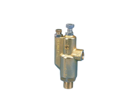
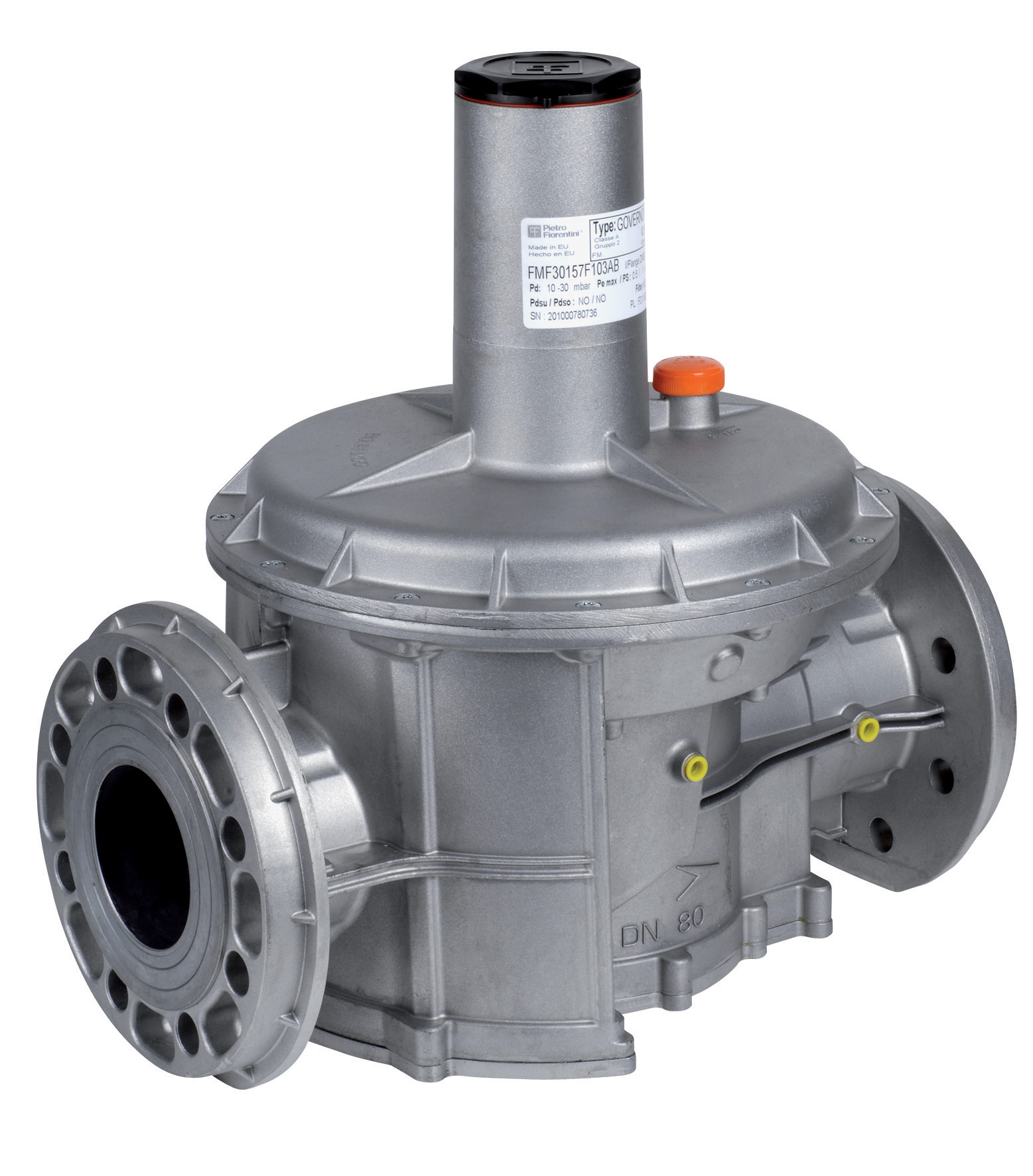
The FAG Pressure Regulator with DN40 Flanges offers integrated strainers and 5-300 mbar adjustability, suitable for precision gas applications requiring clean outlet conditions. Its UNI EN 88 CLASSE A certification ensures reliability in regulated measurement systems.
System Integration and Component Selection Strategy
Multi-Stage Regulation Design
Single-stage regulators cannot simultaneously provide fast response, low hysteresis, and wide flow turndown. Industrial designs typically employ two or three stages:
Stage 1 (Primary Coarse Regulation): Pilot-operated regulator handling full flow range, maintaining ±10% outlet pressure tolerance. Accepts wide inlet pressure swings (e.g., 2.5-5 bar compressed air).
Stage 2 (Secondary Fine Regulation): Direct-acting regulator or solenoid-assisted valve maintaining ±3-5% outlet pressure, handling 20-40% of peak flow. Responds to setpoint signals from process controllers.
Stage 3 (Precision Instrument Regulation): Manual needle valve or vent regulator for field adjustment, protecting sensitive measurement instruments from pressure spikes.
Benefits of Multi-Stage Design:
- Primary stage handles bulk flow, secondary stage fine-tunes pressure
- Reduced pilot flow requirements (efficiency gain of 15-25%)
- Improved response bandwidth (faster load-step response)
- Fault isolation (failure of secondary stage doesn't collapse primary outlet pressure)
Integration with Pressure Vessels and Accumulators
Pressure vessels upstream of regulators act as surge dampers, improving stability. However, improper sizing creates problems:
- Undersized vessel: Pressure swings exceed 20%, regulator hunting persists
- Oversized vessel: Filling time delays exceeds 5-10 minutes; if regulator fails, system depressurizes slowly, causing safety issues
- Incorrect precharge: Nitrogen precharge pressure should be 0.9× minimum operating pressure; higher precharge wastes vessel capacity, lower precharge causes loss of usable volume
For systems with demand swings >100 L/min over <10 seconds, specify accumulator volume of 10-15% of peak flow (measured in liters). Example: 200 L/min peak demand → 20-30 liter accumulator.
Integrating high-pressure hose systems like the Pratissoli Long Life Sewer Cleaning Hoses ZT06B1000353 or Pratissoli Pilotflex 120 Hoses ZT03A0200152 requires accounting for hose internal volume in pressure calculations. 50 meters of 12 mm hose contains ~5.6 liters; under pressure transients, this volume absorbs energy, slowing response time by 2-3 seconds.
Practical Component Selection Workflow
Step 1: Load Analysis
- Document all connected equipment (burners, heaters, measuring instruments)
- Measure or estimate flow rates at design conditions
- Identify duty cycle (continuous, intermittent, pulsed)
- Record inlet pressure range and quality (dry/wet, contamination level)
- Consult equipment manufacturers for required outlet pressure and tolerance band
- Add 0.5 bar safety margin for instruments (prevents shutdown on normal drift)
- Specify maximum allowable pressure for safety relief sizing
- Select regulator rated for 125% peak flow (provides turndown margin)
- Choose response type: pilot-operated for wide flow range (preferred in Singapore for industrial cooling and processing systems), direct-acting for stable supply pressure and light loads
- Specify materials: duplex stainless minimum for coastal locations, carbon steel acceptable >3 km inland if humidity <60%
- Size accumulator based on demand swing analysis
- Select compatible hose/tubing (pressure rating 1.5-2× regulator setpoint)
- Plan vent pathway (ensure pilot and relief gases exit safely, not into enclosed spaces)
- Design inlet filtration (minimum 40 micron absolute for gas regulators, 10 micron for precision instruments)
- Measure and record outlet pressure under no-load and full-load conditions
- Test response time (load step from 25% to 75% of peak flow)
- Document pressure drift over 1-hour steady operation
- Baseline data enables future troubleshooting (drift >10% from baseline triggers inspection)
Maintenance and Troubleshooting Reference
Establish maintenance intervals based on duty cycle and environment:
- Light duty (intermittent use, <5 operating hours/day): Annual inspection, 3-year major overhaul
- Medium duty (continuous operation, stable inlet conditions): Semi-annual inspection, 2-year overhaul
- Heavy duty (pulsed loads, coastal environment, high humidity): Quarterly inspection, annual overhaul
Inspection checklist:
- Visual leakage survey (soap bubble test on all connections)
- Pressure calibration check (compare gauge reading to external pressure standard)
- Response time measurement (load step test, compare to baseline)
- External corrosion assessment (rust on fasteners indicates moisture ingress)
- Sound test (abnormal whistling or chattering indicates internal wear)
Common post-overhaul issues: regulators behave erratically after reassembly if pilot orifices are disturbed. Always use controlled-flow flush procedures with clean, dry nitrogen before pressurizing.
3G Electric's 35-year track record in industrial equipment distribution emphasizes that 80% of regulation problems are preventable through proper initial selection, installation in clean environments, and systematic maintenance. Investing in upstream filtration and environmental protection yields 5-10 year component life; neglecting these fundamentals reduces lifespan to 1-3 years in Singapore's tropical climate.