Understanding Gas Valve Design Architecture
Gas valves & regulation form the backbone of safe industrial gas handling systems. Unlike general-purpose fluid control valves, gas regulation components operate under unique constraints: lower density working media, higher velocity flows, stricter safety requirements, and rigorous international standards compliance.
The fundamental design architecture of gas regulation systems comprises three functional layers: the control valve (primary shut-off or modulation), the pressure regulator (outlet pressure stabilization), and the safety relief mechanism (overpressure protection). These elements work in concert to maintain system integrity across varying demand profiles and supply conditions.
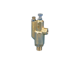
Procurement engineers must understand that gas valve design diverges significantly from liquid valve engineering. Gas compressibility requires different seat materials, spring coefficients, and vent sizing. The Francel B25/37mb pressure regulator with integrated safety relief exemplifies this specialization—its 10 mm vent size and 37 mbar outlet delivery are engineered specifically for laboratory and industrial gas distribution applications where precision and safety relief integration reduce bill-of-materials complexity.
Design considerations include:
- Seat Material Selection: Stainless steel or elastomer seats depending on gas type (inert vs. reactive), temperature range, and duty cycle
- Spring Characteristics: Precise load calculations accounting for gas density variations and altitude compensation
- Vent Configuration: Oversized vents prevent pressure spikes during rapid downstream demand changes
- Pilot Ratio: The relationship between main valve chamber pressure and pilot signal pressure determines response sensitivity
Regulatory Compliance and Standards Framework
Gas valve specification in Singapore and Southeast Asia operates within a stringent regulatory envelope. The primary governing standard is EN 161 (Safety devices for burners and combustion appliances—General requirements), which mandates specific testing protocols, safety margins, and documentation requirements.
Key regulatory touchstones include:
EN 161 Compliance: Defines proof pressure (typically 1.5× nominal working pressure), functional testing sequences, and leak rate acceptance criteria. The Elektrogas VMM 20-25 end-of-stroke contact valve rated for 6 bar incorporates EN 161 design compliance, making it immediately acceptable in regulated gas control applications.
PED (Pressure Equipment Directive): For components rated above 0.5 liters and 25 bar·L, conformity assessment requires third-party certification. Procurement engineers must verify CE marking validity and technical documentation (Module B or C compliance level).
Singapore Standards (SS): Local adoption of ISO/IEC standards requires gas valve suppliers to maintain documentation demonstrating equivalence to recognized international frameworks. 3G Electric's 35+ years as an industrial equipment distributor ensures familiarity with regional compliance nuances and documentation requirements.
Gas Type Compatibility: Valves must be explicitly certified for the specific gas (natural gas, propane, butane, inert gases, toxic gases) due to material compatibility and leak rate implications. Procurement specifications must cross-reference the applicable Conformity Assessment Procedure and gas type designation.
Regulatory gaps often emerge in:
- Flow Capacity Verification: Nameplate flow ratings require independent confirmation through pressure drop calculations
- Environmental Certification: Temperature rating, humidity tolerance, and corrosion resistance validation
- Documentation Chain: Material test certificates, hydrostatic proof certificates, and functional test records must be traceable
Selection Methodology and Application-Specific Criteria
Selecting gas valves & regulation components demands systematic evaluation across technical, economic, and operational dimensions. Procurement engineers should follow a structured methodology that begins with application characterization before component specification.
Step 1: Define System Parameters
Document maximum inlet pressure (accounting for supply fluctuations), nominal outlet pressure requirement, maximum flow rate (peak demand + safety margin), and duty cycle profile (continuous vs. intermittent). For laboratory applications requiring precision and safety integration, the Francel B25/37mb delivers fixed 37 mbar outlet with integrated safety relief, simplifying manifold design.
Step 2: Gas Characterization
Gas type determines material compatibility, density-dependent flow calculations, and regulatory classification. Natural gas systems require different seat materials than inert gas applications. Moisture content in the gas supply influences elastomer seal selection and potential freeze-up risk during rapid expansion.
Step 3: Safety Margin Assessment
Calculate required safety relief capacity to handle maximum credible overpressure scenarios. Relief valve sizing requires:
- Relief set pressure (typically 110% of maximum operating pressure)
- Capacity margin (minimum 20% above maximum anticipated vent flow)
- Vent path design to prevent backpressure on relief discharge
Determine whether the application requires modulating control or on-off switching. End-of-stroke applications favor simple snap-action designs like the Elektrogas VMM 20-25, which provides repeatable switching at 6 bar with minimal adjustment (3 mm Allen wrench access point).
Step 5: Installation Context Review
Evaluate available manifold space, inlet/outlet port threading (ISO/NPT standards), accessibility for maintenance, and environmental exposure (temperature extremes, vibration, corrosive atmosphere). Integrated valve blocks reduce connection points and potential leak sources, though they sacrifice modularity.
System Integration and Performance Optimization
Gas valves & regulation rarely operate in isolation. Procurement engineers must evaluate how component selection affects overall system performance, reliability, and maintenance burden.
Manifold Design Integration
Modern industrial practice favors custom valve manifolds incorporating multiple functions (isolation, regulation, safety relief, pilot solenoids) into single ductile iron or aluminum castings. This approach reduces:
- External port connections (each connection represents a potential leak point)
- Pipeline flexibility requirements
- Footprint in crowded plant installations
- Commissioning complexity
The Francel B25/37mb integrated safety regulator exemplifies this integration—combining main regulation and pilot-controlled safety relief eliminates need for separate relief block, reducing manifold complexity.
Pressure Drop Budgeting
Gas flow through valves creates pressure drop proportional to flow velocity squared. Procurement specifications must reserve adequate supply pressure margin:
- Main valve pressure drop: 2-5% of inlet pressure (typical)
- Regulator pressure drop: 1-3% (quality units)
- Filter pressure drop: 0.5-2% (depending on contamination loads)
- Pilot supply pressure drop: 0.5-1%
Underestimating these drops forces higher inlet pressure, increasing relief valve discharge requirements and system energy consumption.
Pilot Signal Stability
Many modern gas regulators employ pilot-controlled designs where a small downstream pressure signal modulates the main valve. Pilot signal source selection critically affects stability:
- Downstream pilot: Provides proportional response to load changes but risks instability if downstream volume is large
- Upstream pilot with restrictor: Creates hysteresis but provides damping in pulsating applications
- Vent-biased pilots: Add complexity but improve low-pressure regulation accuracy
Procurement engineers should specify pilot configuration explicitly, as vendors may default to designs optimized for different applications.
Maintenance Access and Diagnostics
Operational performance optimization requires planning for routine maintenance. Specifications should require:
- Accessible adjustment screws with clearly labeled directions
- Pressure test points for diagnostics (gauge ports)
- Serviceable cartridge elements rather than sealed units
- Documented setting procedures and lock-wire provisions
With 35+ years distributing industrial equipment, 3G Electric understands that valve selection extends beyond initial specification into long-term operational support. Choosing suppliers with documented local service capabilities, spare parts inventory, and technical documentation availability significantly reduces life-cycle costs.
Contamination Management
Gas valve reliability depends heavily on cleanliness. Industrial gas supplies often contain moisture, particulates, and corrosion products that damage precision surfaces. Procurement strategies should include:
- Coalescent filter sizing (minimum 10 micron absolute)
- Filter pressure differential monitoring
- Regular scheduled filter replacement (typically 2,000-4,000 operating hours)
- Inlet strainers sized for <0.5 bar pressure drop at maximum flow
Regulators with integrated sintered bronze elements provide some inherent filtration but cannot substitute for system-level contamination control.