Understanding Gas Valves & Regulation: Key Differences for Maintenance Teams
Gas Valves & Regulation equipment forms the backbone of safe industrial burner operations. However, maintenance teams often struggle when deciding between different regulator types, pressure ranges, and connection methods. The challenge isn't just selecting a regulator—it's understanding how different configurations perform under various operating conditions and how to maintain them effectively.
With over 35 years of experience distributing industrial equipment globally, 3G Electric has helped thousands of maintenance teams navigate these decisions. The right regulator choice depends on three critical factors: your system's pressure requirements, physical space constraints, and operational reliability needs. A regulator that works perfectly for one application may be inadequate or over-engineered for another.
This guide compares the most common Gas Valves & Regulation options available to industrial maintenance teams, highlighting the practical differences that affect performance, installation, and long-term reliability.
Threaded Versus Flanged Regulators: Installation and Space Considerations
Threaded Connection Regulators
Threaded pressure regulators like the CBM Pressure regulator threaded D1"1/2 500 Mbar PS 5/300 Mbar offer compact, straightforward installation for smaller to medium-sized systems. These units feature NPT or BSPP threaded connections that screw directly into existing piping infrastructure.
Advantages of threaded regulators:
- Faster installation and replacement in confined spaces
- Lower initial cost compared to flanged alternatives
- Easier troubleshooting and field removal without special tools
- Smaller footprint ideal for retrofit applications
- Simpler commissioning procedures
Threaded connections require careful torque application to prevent cross-threading or over-tightening. Maintenance teams should use thread-locking compound on installation to prevent vibration-induced loosening. Replacement typically requires depressurizing the system and disconnecting inlet/outlet lines—a 15-20 minute operation on most systems.
The D1"1/2 size handles moderate flow rates while maintaining pressure stability across a 5-300 mbar operating range, making it suitable for most burner applications operating below medium industrial scale.
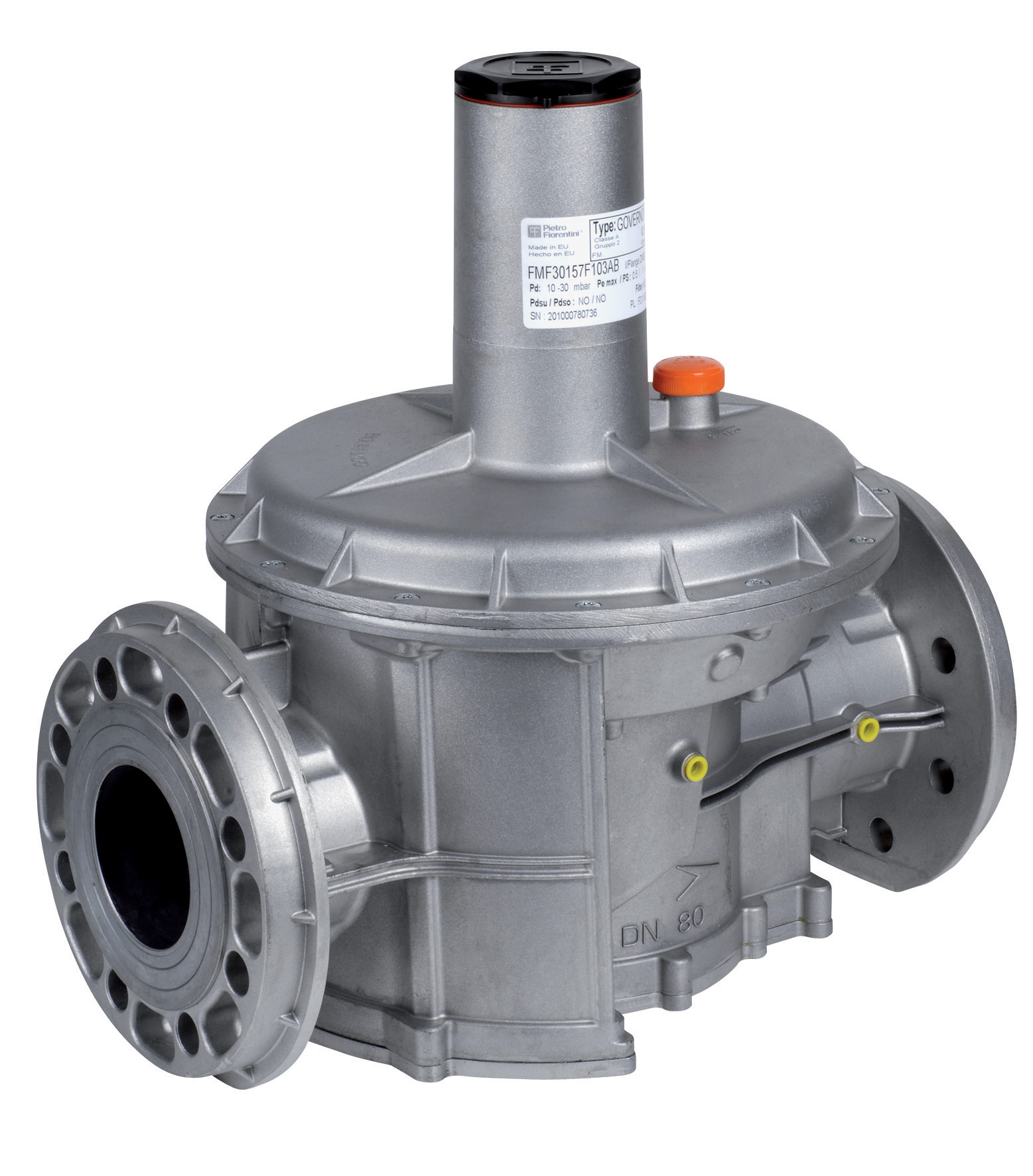
Flanged Connection Regulators
Flanged pressure regulators such as the CBM Pressure regulator with flanges DN50 500 Mbar PS 5/300 Mbar and CBM Pressure regulator with DN65 flanges 500 Mbar PS 5/300 Mbar provide superior stability for larger systems handling higher flow volumes.
Advantages of flanged regulators:
- Bolt-on installation eliminates threading problems
- Better suited for high-vibration industrial environments
- Easier to isolate and replace without disturbing connected piping
- Reduced risk of gas leakage at connection points
- Superior performance in systems operating continuously at capacity
Flanged units require proper gasket selection and bolt torque sequences during installation. DN50 and DN65 sizes represent different flow capacities—DN50 suits medium industrial operations, while DN65 handles larger systems. Both regulators maintain identical 500 mbar inlet pressure with 5-300 mbar outlet range, but DN65 units support proportionally higher gas volumes.
Replacement involves breaking four to eight bolts, removing the gasket, and installing new seals. This takes 30-45 minutes but avoids the threading challenges that sometimes complicate threaded regulator maintenance.
Pressure Range Specifications: Matching Regulators to Your System Requirements
Understanding Inlet Versus Outlet Pressure Ratings
All regulators discussed here operate with 500 mbar maximum inlet pressure and 5-300 mbar outlet pressure range. Maintenance teams frequently misunderstand what these specifications mean in practice.
Inlet pressure (500 mbar) represents the maximum pressure the gas supply delivers to the regulator. Systems supplied from main pipelines or larger tank banks typically operate at 200-400 mbar inlet, leaving safety margin.
Outlet pressure (5-300 mbar) is the controlled pressure the regulator delivers to burners. Most industrial burners operate between 20-100 mbar depending on fuel type and combustion design. The 5 mbar minimum ensures smooth operation even at minimal flame settings.
Maintenance teams should verify their system's actual operating pressures before selecting equipment. A system requiring only 50 mbar outlet functions perfectly with these regulators, but a system needing higher outlet pressure requires different equipment entirely.
Why Oversized Regulators Create Problems
Selecting a regulator rated for 500 mbar inlet when your supply delivers only 150 mbar reduces control precision. The regulator's internal spring and valve seat optimize around their rated range. Operating well below rating causes sluggish response to demand fluctuations and difficulty maintaining steady burner flame.
Conversely, undersized regulators face pressure stability challenges and potential relief valve operation at peak demand, creating safety concerns.
System Integration: Pilot Lights, Safety Controls, and Regulator Selection
Coordinating Pressure Regulation with Safety Systems
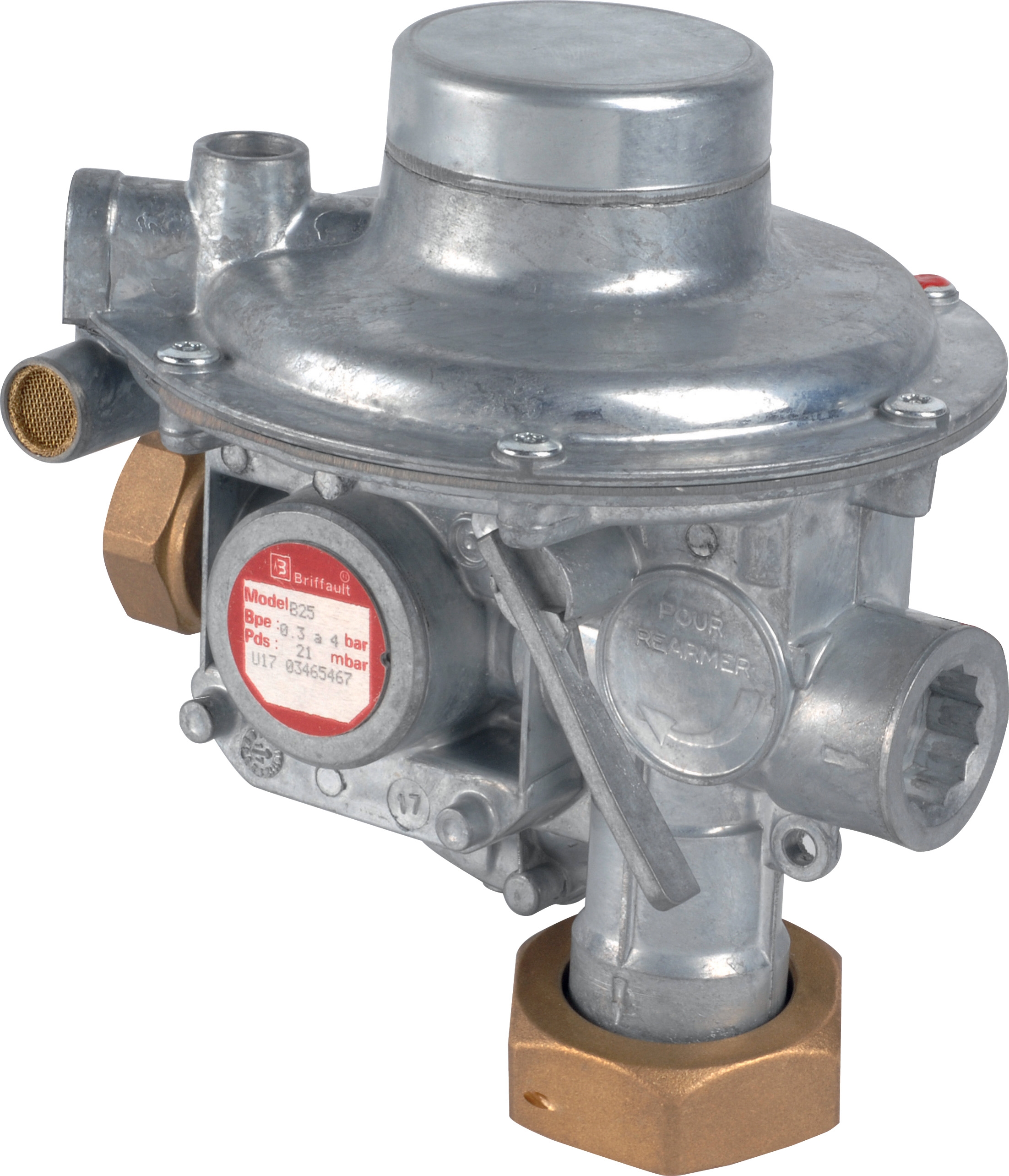
Modern gas systems rarely use pressure regulators in isolation. The CBM Regulator Francel B10/37mbar with safety integrates pressure reduction with safety shutoff capabilities, representing a more complete solution than standalone regulators.
Maintenance teams should understand how pilot light systems like the CBM 1-flame pilot light 0.150.082 interact with pressure regulation:
- Pilot lights typically require 30-50 mbar stable pressure
- Regulators must maintain this pressure even at minimal main burner load
- Safety regulators with integral shutoff protect against over-pressure conditions
- Integrated systems reduce connection points and potential leak sources
Maintenance Workflow Differences
Standalone regulator systems:
Require separate servicing of regulator, pilot light, and safety controls. A regulator failure forces complete burner shutdown until replacement, even if the pilot light functions normally. Testing individual components takes longer, and cross-component issues become difficult to diagnose.
Integrated regulator-safety systems:
Allow independent pilot light operation during regulator maintenance. If the integrated safety regulator fails, the pilot light remaining functional simplifies troubleshooting. However, replacement must be done as a unit, eliminating the option to replace only the damaged component.
Based on 35+ years serving industrial maintenance teams, 3G Electric recommends integrated solutions for critical applications where downtime carries high costs, and standalone regulators for simpler systems where component replacement flexibility matters more.
Practical Maintenance Scenarios: When to Choose Each Regulator Type
Scenario 1: Retrofitting an Older System with Space Constraints
A maintenance team managing legacy equipment in a confined mechanical room faces regulator replacement without expanding infrastructure. The existing piping uses 1½-inch NPT connections.
Best choice: Threaded D1"1/2 regulator allows direct connection to existing piping with minimal modifications. Installation takes two hours including pressure testing and commissioning. The compact design fits existing space without rerouting pipework.
Scenario 2: Upgrading a High-Vibration Industrial System
A maintenance team operates a 24/7 industrial burner system in a facility with significant vibration from adjacent machinery. Recent regulator failures traced back to threaded connection loosening despite thread-locking compound.
Best choice: DN50 flanged regulator eliminates threaded connection failure modes. Bolt-secured connections withstand vibration stress. Initial installation costs more, but reduced maintenance frequency and emergency replacement incidents justify the investment.
Scenario 3: Managing Multiple Burners with Coordinated Pressure Control
A facility operates three separate burner zones, each requiring independent pilot light operation and pressure regulation between 30-80 mbar. Safety shutoff must activate if any zone exceeds 120 mbar.
Best choice: Three integrated safety regulators with coordinated pilot lights provide independent operation and unified safety response. This configuration prevents one zone's failure from affecting others while simplifying maintenance protocols.
Commissioning and Testing: Essential Procedures for New Regulators
After installing Gas Valves & Regulation equipment, maintenance teams must perform specific tests before returning systems to operation:
Pressure validation: Measure inlet and outlet pressure with calibrated gauges at minimum, mid-range, and maximum demand settings. All readings should fall within equipment specifications.
Leak detection: Apply soap solution to all connections while pressurized. Bubbles indicate leaks requiring immediate attention.
Response testing: Activate and deactivate pilot lights while monitoring outlet pressure. Pressure should stabilize within 2-3 seconds.
Safety function verification: For integrated safety regulators, confirm relief valve operation at rated pressure. This requires increasing system pressure until relief activates—perform only with qualified personnel.
Documentation: Record all test results with timestamps and personnel names. This documentation supports warranty claims and regulatory compliance audits.
Long-Term Performance: Maintenance Intervals and Inspection Schedules
Maintenance teams often overlook regulators until failure occurs. Proactive inspection extends equipment life significantly.
Monthly inspection: Visual check for corrosion at threaded or flanged connections. Listen for unusual hissing indicating gas leakage.
Quarterly service: Measure inlet and outlet pressure under normal operating conditions. Compare to baseline readings. Gradual pressure drift indicates internal seal degradation requiring replacement.
Annual overhaul: Deep inspection of internal components for particulate contamination. Gas system contamination shortens regulator lifespan; inline filtration upstream of all regulators prevents this damage.
Replacement schedule: Industry standards recommend regulator replacement every 5-7 years even without observed failure. Internal springs lose elasticity over time, reducing pressure stability.
With 35 years supporting global industrial operations, 3G Electric has documented that maintenance teams performing these inspections experience 60-70% fewer emergency failures and equipment downtime.
Conclusion: Building a Reliable Gas Regulation Strategy
Gas Valves & Regulation selection extends beyond choosing between regulator types. It involves understanding your system's specific pressure requirements, installation constraints, and integration with pilot lights and safety systems. Whether you select threaded simplicity, flanged robustness, or integrated safety solutions depends on your operational priorities.
Maintenance teams equipped with this knowledge avoid costly missteps, reduce unplanned downtime, and build systems that operate reliably for years. 3G Electric's partnership with leading manufacturers like CBM ensures access to proven equipment and expert guidance throughout your system's lifecycle.