Understanding Fluid System Performance Degradation
Fluid system performance decline represents one of the most costly yet preventable issues facing Singapore's industrial plant managers. When flow rates drop or pressure readings become erratic, production schedules suffer immediately. Yet many facilities treat these symptoms reactively rather than investigating root causes systematically.
With over 35 years of experience distributing industrial equipment across Southeast Asia, 3G Electric has observed that approximately 60-70% of reported pump failures stem not from component wear but from maintenance & service oversights that compound over time. The challenge is that fluid system performance degradation develops gradually, making it easy to miss early warning signs until catastrophic failure forces shutdown.
This troubleshooting guide focuses on practical diagnostic methods that plant managers can implement immediately to identify performance issues before they escalate. Understanding the relationship between system pressure, flow rate, temperature, and component efficiency allows you to make informed decisions about repair timing and resource allocation.
Diagnosing Abnormal Flow Rate Decline
Establishing Your Baseline Flow Rate
Before troubleshooting flow rate problems, you must establish what "normal" actually means for your specific system. Every installation differs based on pump displacement, motor speed, system configuration, and operational load. Document your system's rated flow rate from pump specifications, then measure actual output under standard operating conditions.
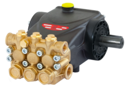
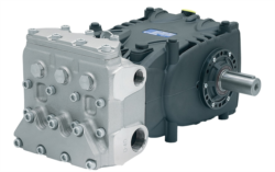
For high-performance pumps like the Interpump PUMP E2C2111 L, rated at 11 L/min at 210 bar, any sustained output below 10.5 L/min signals potential issues. Similarly, the Pratissoli KF30 delivers 106 L/min at 200 bar—measuring consistent output at 95 L/min or less indicates degradation requiring investigation.
Common Causes of Flow Rate Decline
Once you confirm flow rate loss, investigate these factors in order:
Internal Leakage represents the primary cause in systems running beyond their design pressure envelope. High-pressure pump seals develop microscopic gaps as they age. The Interpump PUMP SSU2040 R ATEX operating above rated bar pressure for extended periods will show internal leakage manifesting as reduced output while maintaining system pressure. You cannot resolve internal leakage through component cleaning—replacement becomes necessary.
Inlet Restriction reduces available suction pressure, preventing the pump from drawing full fluid volume. Check filter pressure gauges (ideally installed between tank and pump inlet). Filters showing pressure differential exceeding manufacturer specifications restrict flow. Singapore's humid climate accelerates water contamination in hydraulic systems; water-contaminated fluid degrades filter efficiency rapidly. Inspect filters monthly and replace if bypass indicators activate or pressure differential exceeds 0.5 bar at normal operating flow.
Cavitation occurs when inlet pressure drops below vapor pressure, causing fluid vaporization inside pump chambers. This creates vapor pockets that collapse violently, reducing effective flow and generating characteristic acoustic noise (sounding like gravel flowing through pipes). Cavitation destroys pump internals within hours if unaddressed. Verify inlet line diameter matches pump specifications, eliminate sharp bends in suction lines, and maintain inlet temperature below 50°C.
Viscosity Mismatch fundamentally affects flow characteristics. If maintenance personnel switch to non-approved hydraulic fluid or if system temperature climbs, fluid viscosity changes dramatically. High viscosity increases internal friction, reducing flow output. Low viscosity increases internal leakage, also reducing net flow. Always verify that fluid viscosity matches pump specifications and monitor system temperature continuously. Most systems perform optimally at 40-50°C.
Systematic Diagnostic Procedure
When flow rate decline exceeds acceptable thresholds, follow this sequence:
1. Verify gauge accuracy by cross-checking with certified test instruments
2. Measure inlet pressure—should show minimal restriction (typically less than 0.2 bar differential)
3. Inspect and test suction filters for bypass activation
4. Confirm fluid viscosity and temperature readings
5. Check pump case drain line for backpressure (should be near zero)
6. Measure case drain fluid temperature—elevated temperatures indicate internal leakage
7. Document flow rate decline rate (gradual versus sudden drops indicate different causes)
Resolving Pressure Inconsistency and Instability
Distinguishing Pressure Fluctuation Types
Pressure instability manifests in two distinct patterns, each indicating different underlying issues:
Oscillating Pressure (rapid fluctuations between two values, typically 5-20 bar variance) usually originates from relief valve chattering or pump swashplate instability in variable displacement units. Relief valves designed for smooth pressure regulation can malfunction if contamination deposits accumulate on the spool seat. Fluid contamination represents the primary culprit in Singapore's industrial environments where dust infiltration occurs readily.
Drifting Pressure (steady decline or increase over minutes rather than rapid fluctuation) points toward pilot pressure system failures, compensator malfunctions, or load-induced issues. The Interpump W2035 L ATEX maintains consistent 200 bar output through precision pressure compensation; if actual output drifts below setpoint, the compensator requires investigation or replacement.
Contamination as the Root Cause
Contamination creates 70% of all pressure instability issues plant managers encounter. Particulate contamination (sand, rust, wear particles) lodges in valve seats and compensator spools, preventing smooth operation. Water contamination causes corrosion of precision surfaces, creating micro-scratches that disrupt sealing.
Implement robust fluid management:
- Install offline fluid analysis capabilities (quarterly testing minimum in Singapore's climate)
- Maintain inlet and breather filters with moisture-absorbing media
- Drain accumulated water from tank sumps monthly
- Conduct oil analysis focusing on particle count (ISO cleanliness target: 16/14/11 or better)
- Replace fluids on calendar schedules regardless of appearance
Pressure relief valves maintain system safety but require precise adjustment and cleanliness. When pressure instability occurs:
1. Isolate the relief valve from the system
2. Flush the spool cavity with approved cleaning fluid
3. Inspect the spool and seat for scoring or deposits using magnification
4. If damage appears minor (light scratches), attempt polishing with fine emery paper
5. If seat damage proves extensive, replacement becomes necessary—repair attempts create safety liabilities
6. After cleaning, adjust relief pressure to specification using calibrated test equipment (not trial-and-error adjustments)
Never attempt field repair of relief valve seats without proper tools and training. Incorrect adjustment can cause system overpressure, creating equipment damage and personnel hazards.
Temperature-Induced Pressure Changes
Singapore's tropical climate creates ambient temperatures 28-32°C regularly. Fluid temperature increases correlate directly with pressure changes (approximately 0.6 bar per degree Celsius in confined systems). This temperature sensitivity explains apparent pressure instability that actually represents normal thermal response.
Install temperature monitoring at pump discharge. If temperature climbs above 55°C, investigate cooler capacity. Most industrial systems require cooler capacity matching 10-15% of system flow rate (for a 100 L/min system, a cooler removing approximately 10-15 kW maintains acceptable temperature). Undersized coolers create persistent pressure inconsistency that worsens throughout operating days.
Maintenance & Service Strategies for Optimal Component Performance
Preventive Maintenance Scheduling
3G Electric's three-plus decades serving Southeast Asian industrial operations demonstrates that systematic preventive maintenance reduces unplanned downtime by 60-70% compared to reactive repair approaches. Establish maintenance intervals based on operating hours rather than calendar dates:
Every 250 Operating Hours:
- Visual inspection of pump housing and connections for leakage
- Temperature verification under full load
- Pressure gauge accuracy check (using certified test instrument)
- Suction filter condition assessment
- System noise analysis (audible changes indicate developing problems)
- Fluid sample analysis (particle count, water content, viscosity)
- Tank inspection and sediment removal
- Relief valve bench testing
- Case drain system inspection
- Coupling alignment verification
- Seal and bearing inspection in accessible locations
- Pump displacement verification (flow rate testing under controlled conditions)
- Pressure relief valve full recertification
- System flushing if fluid analysis indicates contamination approaching acceptable limits
- Cooler core inspection and cleaning
- Complete pump disassembly and inspection (if accumulated operating hours exceed 5,000)
- Seal replacement regardless of condition (preventive approach costs 40% less than emergency replacement)
- Bearing inspection and lubrication
- Pressure compensator cleaning and testing
- System component replacement based on accumulated hours and stress analysis
Maintain detailed maintenance records capturing:
- Actual operating hours (separate from calendar time)
- All pressure and temperature readings under standardized load conditions
- Fluid analysis results with date and sample location
- Any repairs or component replacements with part numbers and labor hours
- Anomalies or performance changes noted by operators
This documentation enables trend analysis. When you plot pressure readings over 6-month periods, developing issues become visible weeks or months before failure. Temperature trends reveal cooler degradation. Flow rate measurements quantify performance degradation rate.
Component Selection for Extended Service Life
When repairs require pump replacement, specify equipment engineered for your specific duty. The Interpump PUMP E2C2111 L suits high-pressure, lower-volume applications (11 L/min at 210 bar), while the Pratissoli KF30 addresses applications requiring higher flow (106 L/min at 200 bar). Matching pump displacement to actual system requirements extends service intervals and reduces operating stress.
For hazardous environments, equipment like the Combutech Flame relay CF1 requires specialized maintenance protocols. Combustion detection systems demand annual calibration and sensor inspection, as contamination affects UV detector responsiveness. Neglecting flame detector maintenance creates serious safety compliance issues in Singapore's stringent regulatory environment.
Common Questions and Practical Solutions
Plant managers frequently encounter similar troubleshooting scenarios. The following section addresses questions emerging consistently across Singapore industrial operations:
Question: How do I determine whether my pressure gauge reading is accurate?
Answer: Install a certified test gauge with matching range specifications alongside your system gauge and compare readings under full operating load—readings should match within 2% of full scale. Test gauges require annual calibration; budget for this essential verification tool.
Question: What fluid temperature constitutes an emergency shutdown condition?
Answer: Temperatures exceeding 60°C create rapid seal degradation and fluid oxidation; operating above 65°C requires immediate shutdown for investigation. Most hydraulic fluids approach viscosity limits around 70°C, reducing lubrication effectiveness and increasing component wear exponentially.
Question: Can I extend pump service intervals if my system shows stable performance?
Answer: No—extending maintenance intervals below manufacturer recommendations creates cumulative damage invisible until catastrophic failure occurs. Preventive maintenance identifies developing issues before they cause production stoppage; reactive approaches cost significantly more over equipment lifetime.
Question: How frequently should I replace hydraulic fluid in Singapore's humid climate?
Answer: Most industrial systems in Southeast Asia require complete fluid replacement every 3,000-4,000 operating hours due to moisture infiltration; cooler climates allow 5,000+ hour intervals. Quarterly fluid analysis determines actual contamination progression for your specific installation.
Question: What's the relationship between pump displacement and system pressure reliability?
Answer: Higher displacement pumps at lower pressures generate less internal stress than lower displacement pumps forced to deliver the same pressure—oversizing pump displacement moderately (10-15% above minimum requirement) extends service life considerably while reducing heat generation.
Conclusion: From Reactive Repair to Predictive Maintenance
The transition from reactive troubleshooting to predictive maintenance represents the most significant operational improvement plant managers can implement. Rather than responding to failures, you'll identify developing issues systematically, schedule maintenance during planned downtime, and eliminate emergency repairs disrupting production schedules.
3G Electric's 35+ years supplying Southeast Asian industrial operations confirms that plants implementing systematic maintenance & service protocols experience:
- 50-60% reduction in unplanned downtime
- 30-40% extension of pump service intervals
- 25-35% lower overall ownership costs
- Improved safety compliance and operator confidence
The troubleshooting methodologies outlined above translate immediately into operational improvements. Start by establishing accurate baseline measurements for your existing systems, then implement the diagnostic procedures as part of regular maintenance cycles. Document findings consistently, analyze trends monthly, and adjust maintenance intervals based on actual performance data rather than assumptions.
Your fluid system maintenance & service investments today prevent costly failures tomorrow. By understanding the diagnostic procedures for flow rate decline, pressure inconsistency, and component performance issues, you position your facility for sustained reliability and optimal productivity.