Flame Detection Sensor Failures in Burner Controls: Diagnostic Troubleshooting Guide for Global Industrial Operations
Flame detection sensors are critical safety components in modern burner control systems, yet they remain one of the most frequently misdiagnosed failure points in industrial facilities globally. When a flame sensor fails, the entire burner system enters a protective lockout state—a deliberate safety response that halts operations until the underlying issue is resolved. For maintenance teams and service engineers, understanding the root causes of sensor failures and implementing systematic diagnostic procedures is essential for minimizing downtime and maintaining safe, efficient burner operation. This guide provides the technical knowledge and practical troubleshooting methodology needed to quickly identify, diagnose, and resolve flame detection sensor issues across different sensor technologies and burner configurations.
Understanding Flame Detection Technology in Burner Control Systems
Flame detection sensors operate on three primary physical principles: infrared radiation detection, ultraviolet radiation detection, and phototransistor light sensing. Each technology responds to different spectral characteristics of the flame, making sensor selection critical to system reliability. Infrared sensors detect heat radiation emitted by the flame, making them suitable for both oil and gas burner applications. Ultraviolet sensors detect the ionization effects present in flames, offering rapid response times but requiring precise spectral alignment. Phototransistor-based sensors detect visible light wavelengths from the flame, providing stable, long-term performance in many industrial applications.
The flame supervision circuit works by establishing a safety chain: the burner ignition system fires the pilot light or main burner, the flame sensor detects the presence of flame within a defined time window (typically 1-3 seconds), and the control module maintains burner operation. If the sensor fails to confirm flame presence during the ignition cycle, the control system triggers a non-volatile lockout—a safety shutoff that prevents continuous gas or fuel flow into an unlit burner. This protective mechanism prevents dangerous accumulation of unburned fuel and potential explosion hazards. Understanding this safety architecture is foundational to effective troubleshooting, as sensor failures can manifest as either failure-to-ignite conditions or unexpected lockouts during normal operation.
Environmental factors significantly impact sensor performance across global industrial applications. Thermal cycling stress from rapid temperature fluctuations, moisture infiltration in humid tropical climates, carbon buildup on optical surfaces, and vibration-induced connector loosening all contribute to sensor degradation. Additionally, the spectral characteristics of different fuel types—yellow flames from oil burners versus blue flames from gas burners—require matching sensor technology to fuel application. Selecting the wrong sensor type or operating outside environmental design specifications represents a common source of preventable failures in maintenance practice.
Technical Specifications and Diagnostic Components for Flame Sensor Systems
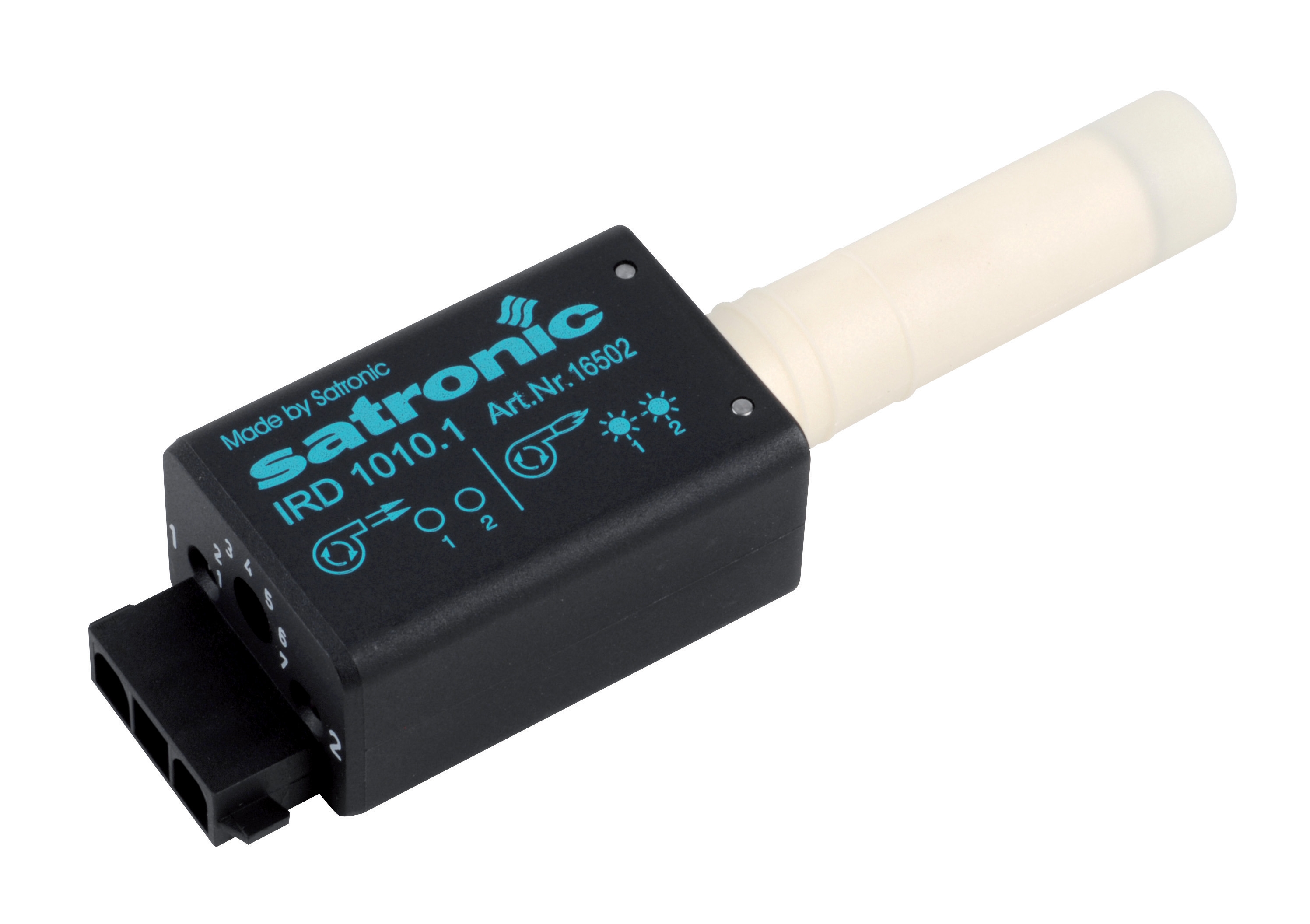
The CBM IRD 1010 blue cell represents a primary infrared flame detection technology designed specifically for fuel oil surveillance. This infrared detector operates by sensing radiant heat from the flame at specific wavelengths, providing reliable detection for yellow oil flames and blue flames under various burner conditions. The IRD 1010 connects to automatic control modules through standard safety relay systems, allowing immediate burner shutdown if the flame signal is lost. Typical response time ranges from 2-4 seconds, accommodating both intermittent-duty burners and extended operation cycles. The blue cell variant optimizes sensitivity for blue flame detection, commonly encountered in modern low-emission burner designs.
For gas burner applications with different flame characteristics, the CBM FC11 phototransistor flame sensor (now replaced by the FT11-V variant) provides an alternative detection methodology. Phototransistor-based sensors detect visible light wavelengths emitted by flames, offering superior performance in applications where infrared saturation or background radiation interference occurs. These sensors feature built-in phototransistor elements compliant with RoHS 2011/65/EU directives and provide excellent long-term stability in industrial environments. Operating windows typically span 380-780 nanometers of visible spectrum, making them responsive to both yellow and blue flame colors. The key diagnostic advantage of phototransistor sensors is their simplified electrical interface—a straightforward light-activated transistor—which simplifies troubleshooting to basic signal continuity testing.
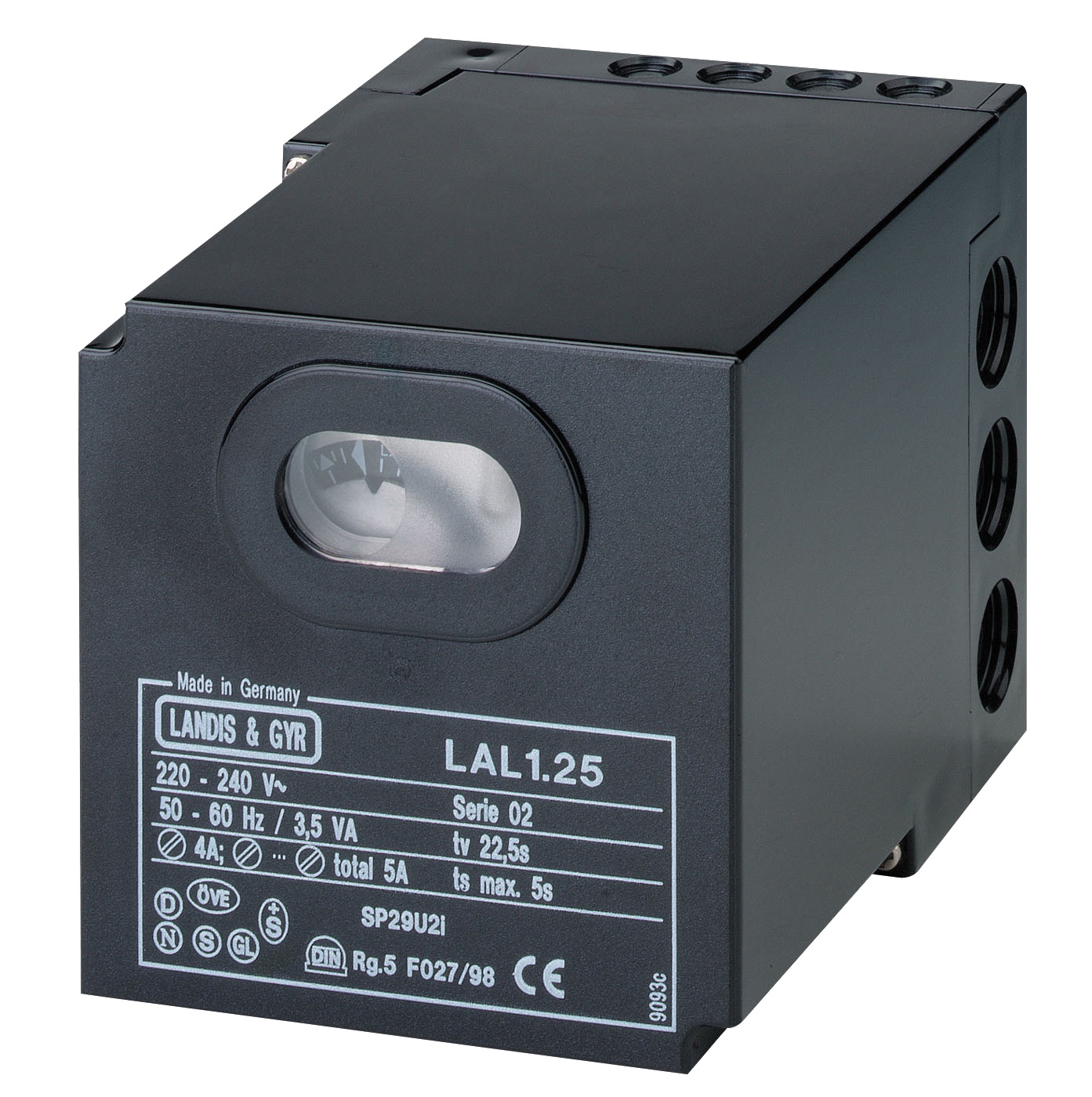
System-level flame supervision integration occurs through safety relay modules such as the CBM LAL 2.14 safety relay, which provides integrated flame monitoring, air pressure control verification, and controlled air damper operation for oil burners. This relay accepts sensor input signals and enforces the safety interlock chain: air pressure must be verified, flame must be confirmed within the ignition window, and continuous flame presence must be maintained during operation. The LAL 2.14 includes manual reset functionality for lockout recovery, allowing service engineers to identify and clear fault conditions before system restart. Understanding the complete signal chain from sensor → relay module → control output is essential for isolating whether failures originate in the sensor itself or in the relay module's signal processing circuitry.
The CBM Minisit gas control block 0710750 integrates flame supervision with pressure regulation and temperature control in a single multifunctional device, commonly deployed in boilers, stoves, and catering equipment. This integration requires diagnostic procedures that distinguish between sensor failures and control module failures, as identical symptoms (no ignition, lockout) can originate from different subsystems. The thermoelectric flame supervision input on multifunctional blocks provides a test point that allows isolation of sensor performance from overall system operation—a critical diagnostic distinction for efficiency in field troubleshooting.
Real-World Diagnostic Scenarios and Failure Modes
A common failure scenario across global industrial facilities involves the infrared sensor accumulating carbon deposits on its optical window. In oil-fired burners operating in facilities with suboptimal fuel quality or combustion efficiency, carbon byproducts deposit on the sensor lens over months of operation. This reduces light transmission to the infrared detector by 40-70%, causing the sensor to report diminished or absent flame signals even though visible flame is present. The burner enters repeated lockout cycles because the control module perceives insufficient flame confirmation. Diagnostic confirmation involves visual inspection of the sensor window (which will appear dark or cloudy rather than clear), measurement of sensor output voltage using a calibrated meter before and after gentle cleaning with approved solvents, and comparison to manufacturer baseline specifications. Recovery requires cleaning the sensor with non-abrasive, non-conductive materials and verification that output voltage returns to design range.
A second prevalent failure involves moisture infiltration in humid tropical and subtropical climates where facilities lack rigorous environmental controls on electrical enclosures. Flame sensors exposed to condensation or salt spray in coastal industrial zones experience corrosion of connector contacts and internal circuitry degradation. Diagnostic indicators include intermittent lockout cycles (sensor signal momentarily lost then recovered), higher-than-normal sensor output voltage variation, and visible corrosion on connector pins or sensor housing. Remediation requires replacement of the sensor assembly and implementation of environmental controls—such as conduit sealing, silica gel desiccant packs in control cabinets, and regular IP-rated connector maintenance—to prevent recurrence.
A third failure mode specific to phototransistor sensors involves incorrect optical alignment after burner servicing or component replacement. The sensor position relative to the flame envelope determines the quantity and spectral composition of light reaching the phototransistor. Misalignment by 15-25 degrees (common when technicians reassemble burner components without proper positioning) reduces signal strength below the relay module's detection threshold. Unlike carbon fouling, cleaning provides no improvement. Diagnostic confirmation requires measurement of sensor output under full illumination (sensor positioned correctly toward flame), comparison to baseline specifications (typically 3-5 volts in good light, 0.2-0.5 volts in darkness), and repositioning of the sensor assembly to restore optimal alignment. Documentation of correct sensor position—using alignment marks, position photos, or installation diagrams—prevents misalignment on future maintenance cycles.
Systematic Troubleshooting Methodology for Flame Sensor Diagnosis
Effective flame sensor troubleshooting follows a hierarchical diagnostic sequence that isolates variables and converges on the root cause efficiently. Begin with visual inspection: examine the sensor window for carbon deposits, corrosion, or physical damage; verify connector integrity and the absence of corrosion on pins; confirm the sensor is mechanically secured and aligned toward the flame zone. Proceed to electrical continuity testing: measure sensor output voltage under dark conditions (should be minimal, typically <0.5V), then direct controlled light or an infrared source at the sensor and measure output voltage change (should increase significantly, typically 3-5V or greater depending on sensor type). If voltage output does not change with light exposure, suspect internal sensor failure requiring replacement.
Next, isolate the relay module from the sensor: if possible, temporarily apply a known-good sensor signal (using a signal generator set to output appropriate voltage/frequency) to the relay module input while observing whether the relay responds correctly. If the relay functions with an external signal but fails with the actual sensor, the sensor itself requires replacement. If the relay fails to respond to either signal, the relay module's input circuitry is faulty. Document all voltage measurements, environmental conditions, and operational observations for future reference and predictive maintenance planning.
Finally, verify correct sensor selection for the application: confirm that the sensor type (infrared, ultraviolet, or phototransistor) matches the fuel type (gas versus oil), that the spectral response matches the expected flame color, and that environmental operating conditions (temperature, humidity, vibration) fall within manufacturer specifications. Sensor selection errors account for approximately 15-20% of recurring flame detection failures in industrial facilities globally.
Best Practices for Sensor Selection and Long-Term Reliability
Select flame detection sensors based on fuel type compatibility, environmental conditions, and proven performance in your specific facility class. Oil-fired burners with yellow flame characteristics require infrared sensors such as the IRD 1010, which provide optimal spectral response for combustion radiation in the infrared band. Gas burners with blue flames benefit from phototransistor-based detection such as the FC11 sensor, which responds effectively to visible blue flame emission. Environmental factors—humidity levels, temperature cycling, salt spray exposure, and vibration intensity—must all factor into sensor selection. For tropical and coastal facilities, specify sensors with enhanced corrosion resistance and integrate environmental controls (sealed conduit, desiccant packs, regular connector maintenance) into the maintenance protocol.
Implement preventive maintenance intervals based on facility operating hours and environmental severity: for standard industrial applications, inspect and test flame sensors every 500-1,000 operating hours or annually; for high-severity environments (coastal salt spray, high humidity), reduce intervals to 250-500 operating hours. Establish baseline reference measurements (sensor output voltage in dark and under flame illumination) within the first 50-100 operating hours of new sensor installation, then monitor these measurements against baseline to detect degradation trends before failures occur. Replace sensors proactively when output measurements drift beyond ±15% of baseline, preventing unexpected lockouts during critical operational periods.
Maintain accurate documentation of sensor installations, including position photos, alignment angles, connector types, and baseline performance measurements. This documentation enables rapid identification of correct replacement sensors and simplifies troubleshooting on subsequent failure events. For systems using integrated control blocks such as the Minisit gas control block, document the specific sensor type and flame supervision input characteristics, as these vary among different control block generations.
Connecting with 3G Electric for Expert Guidance
Flame detection sensor failures require precise technical knowledge and access to reliable replacement components. Whether you're troubleshooting unexpected lockouts, managing preventive maintenance programs, or selecting sensors for new burner installations, the technical team at 3G Electric provides expert guidance based on over three decades of experience in industrial equipment distribution. We maintain stock of flame detection sensors, safety relay modules, and multifunctional gas control blocks from leading manufacturers, ensuring rapid replacement availability when failures occur. Contact 3G Electric to discuss your specific flame detection challenges, obtain detailed technical specifications for your burner configuration, or arrange training for your maintenance team on flame sensor diagnostics and best practices. Our team is prepared to support your facility's safety, efficiency, and operational reliability across global industrial operations.